IDEC SmartRelay installation and wiring
IDEC SmartRelay Manual 39
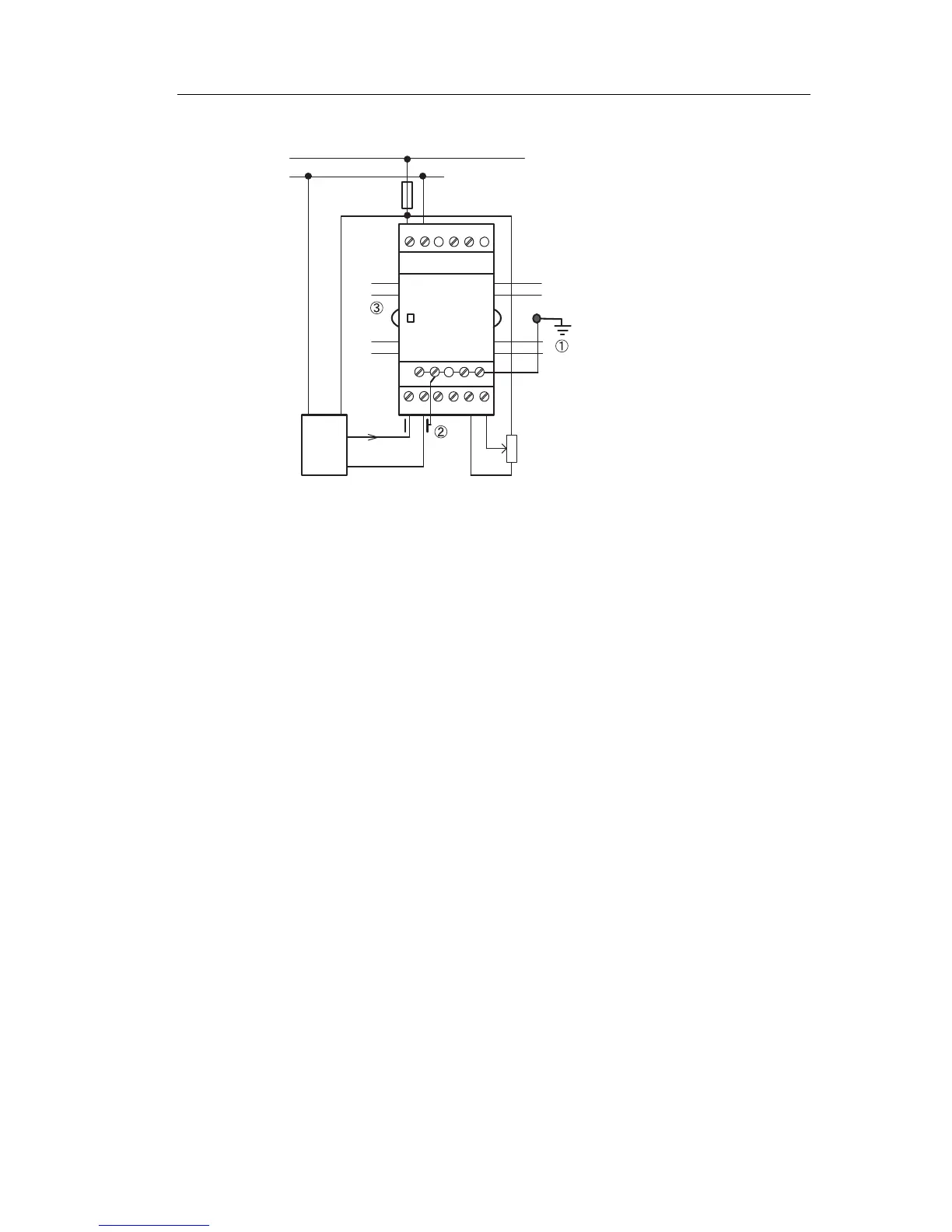
FL1B-J2B2
The illustration above shows an example of four–wire
current measurement and two–wire voltage measurement.
Connecting a two–wire sensor to the FL1B-J2B2
Wire up the two–wire sensor’s connecting wires as follows:
1. Connect the sensor’s output to connection U (0 ... 10 V
vo
ltage
measurement) or to connection I (0 ... 20 mA
current measurement) of the FL1B-J2B2 module.
2. Connect the plus connector on the sensor to the 24 V
supply voltage (L+)
.
3. Connect the ground connection of the current output M
(on the righ
t side of the sensor, as shown in the figure
above) to the corresponding M input (M1 or M2) on the
FL1B-J2B2 module.