EasyManuals Logo
Home>IDEC>Control Unit>SmartRelay Series

IDEC SmartRelay Series User Manual

IDEC SmartRelay Series
297 pages
To Next Page IconTo Next Page
To Previous Page IconTo Previous Page
Page #113 background imageLoading...
Page #113 background image
IDEC SmartRelay functions
IDEC SmartRelay Manual 103
4.2.6 NOR (NOT OR)
The output status of the NOR is only 1 if all inputs are 0, i.e.
if switched off. The NOR output is set to 0 when one of the
inputs is switched on (logical 1 status).
At an unused block input (x): x = 0.
Table of the NOR logic
1234Q
00001
00010
00100
00110
01000
01010
01100
01110
10000
10010
10100
10110
11000
11010
11100
11110
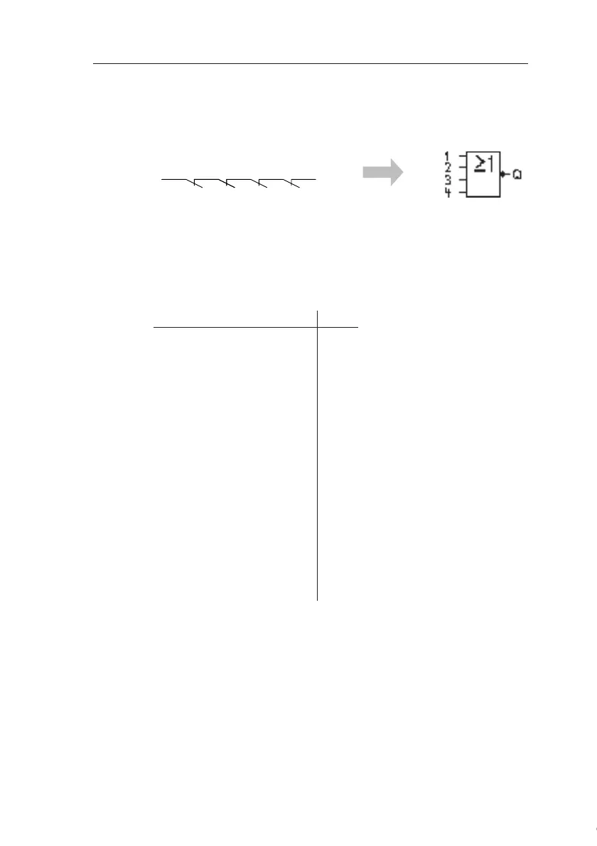
Symbol in IDEC SmartRelay:
Circuit diagram of a series circuit
with several break contacts:
Courtesy of Steven Engineering, Inc. ● 230 Ryan Way, South San Francisco, CA 94080-6370 ● General Inquiries: (800) 670-4183 ● www.stevenengineering.com

Table of Contents

Questions and Answers:

Question and Answer IconNeed help?

Do you have a question about the IDEC SmartRelay Series and is the answer not in the manual?

IDEC SmartRelay Series Specifications

General IconGeneral
BrandIDEC
ModelSmartRelay Series
CategoryControl Unit
LanguageEnglish

Related product manuals