Programming IDEC SmartRelay
IDEC SmartRelay Manual 55
3.6.2 The first circuit program
Let us now take a look at the following parallel circuit consist-
ing of two switches.
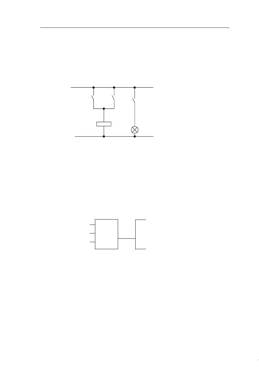
Circuit diagram
The corresponding circuit diagram:
Translated into a IDEC SmartRelay circuit program this
means: Relay K1 is at output Q1 is controlled by means of
an OR block.
Circuit program
S1 is connected to the I1 and S2 to the I2 input connector of
the OR block.
The corresponding layout of the circuit program in IDEC
SmartRelay:
K1
S1
K1
S2
E1
The load is switched on with
S1 OR S2. IDEC SmartRelay
interprets this parallel circuit as
an ‘OR’ logic, because S1 OR
S2 switches on the output.
Courtesy of Steven Engineering, Inc. ● 230 Ryan Way, South San Francisco, CA 94080-6370 ● General Inquiries: (800) 670-4183 ● www.stevenengineering.com