Programming IDEC SmartRelay
IDEC SmartRelay Manual 41
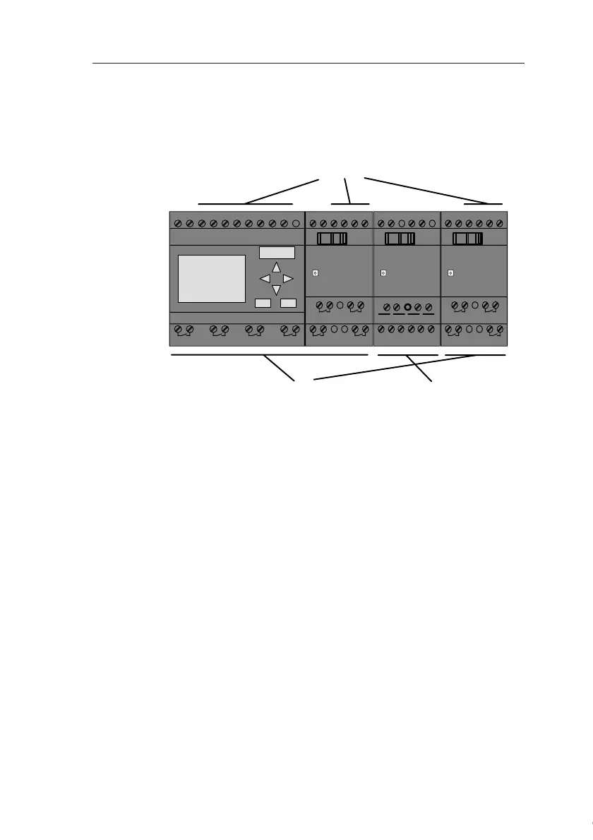
3.1 Connectors
The IDEC SmartRelay is equipped with inputs and outputs
Example of a configuration with several modules:
Each input is identified by the letter I plus a number. When
you take a look at the IDEC SmartRelay from the front, you
can see the input terminals at the top. Only the analog mod-
ules FL1B-J2B2 has the inputs at the bottom.
Each output is identified by the letter Q plus a number. In the
figure, you can see the output terminals at the bottom.
L+ M I13I14I15I16
Q11
Q9
Q12
Q10
RUN/STOP
L+ M
A!3
RUN/STOP
L+ M I1 I2 I3 I4 I5 I6
Q1 Q2 Q3 Q4
AI1 AI2 L+ M I9 I10I11I12
Q7
Q5
Q8
Q6
RUN/STOP
M3U3AI4M4 U4
1 2 1
2
1 2 1 2
1 2 1 2 1 2 1 2
1 2 1 2
1 2 1 2
PE
INPUT 2x (..10 V/..20 mA)
L+ M
Inputs
Outputs Analog Inputs
Courtesy of Steven Engineering, Inc. ● 230 Ryan Way, South San Francisco, CA 94080-6370 ● General Inquiries: (800) 670-4183 ● www.stevenengineering.com