EasyManuals Logo
Home>IDEC>Control Unit>SmartRelay Series

IDEC SmartRelay Series User Manual

IDEC SmartRelay Series
297 pages
To Next Page IconTo Next Page
To Previous Page IconTo Previous Page
Page #66 background imageLoading...
Page #66 background image
Programming IDEC SmartRelay
56
IDEC SmartRelay Manual
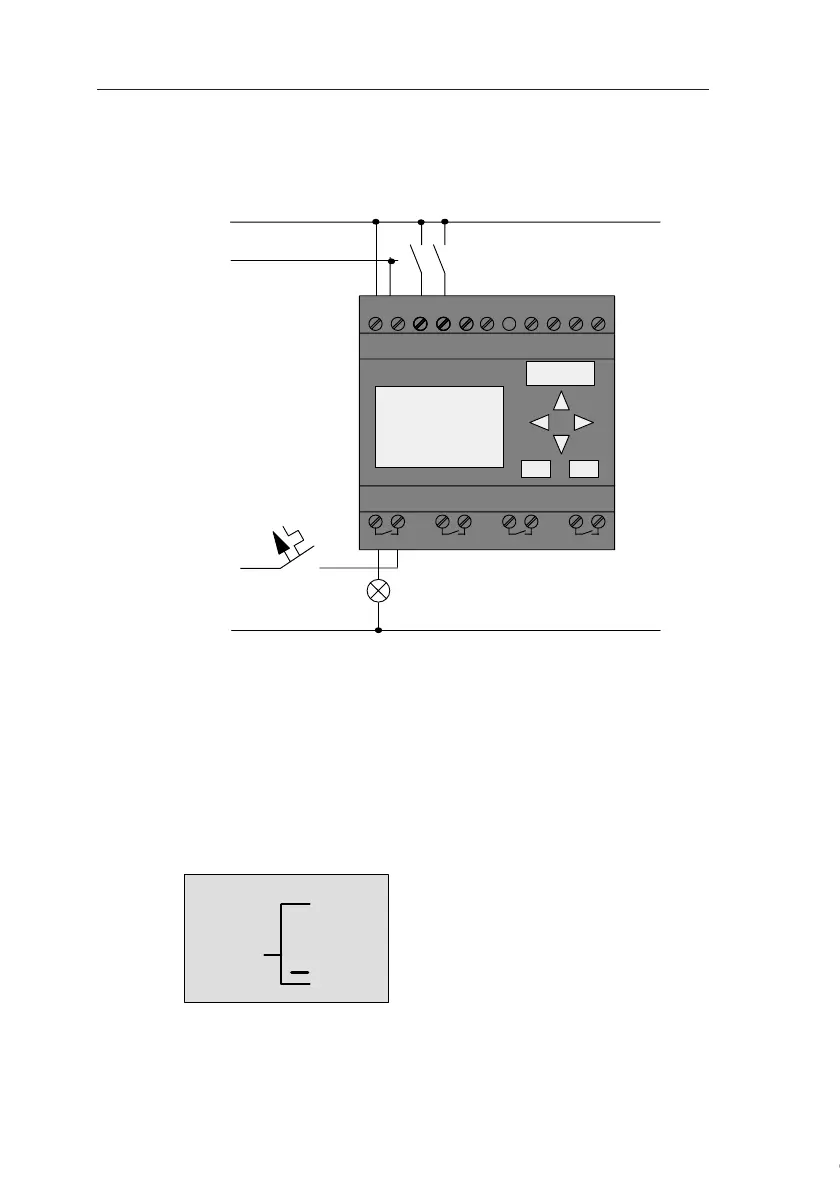
Wiring
The corresponding wiring:
S1 switches input I1, while S2 switches input I2. The load is
connected to the relay Q1.
3.6.3 Circuit program input
Let us now write the circuit program, starting at the output
and working towards the input. IDEC SmartRelay initially
shows the output:
L1 N I4 I5 I6I7I8
Q1 Q2 Q3 Q4
L1
N
S1
S2
L
N
I1I1 I3I1I1 I1I1I1I2
1 2 1 2 1 2 1 2
Q1
The first IDEC SmartRelay output
Courtesy of Steven Engineering, Inc. ● 230 Ryan Way, South San Francisco, CA 94080-6370 ● General Inquiries: (800) 670-4183 ● www.stevenengineering.com

Table of Contents

Questions and Answers:

Question and Answer IconNeed help?

Do you have a question about the IDEC SmartRelay Series and is the answer not in the manual?

IDEC SmartRelay Series Specifications

General IconGeneral
BrandIDEC
ModelSmartRelay Series
CategoryControl Unit
LanguageEnglish

Related product manuals