Programming IDEC SmartRelay
IDEC SmartRelay Manual 47
3.3 The way to IDEC SmartRelay, starting with
the circuit diagram
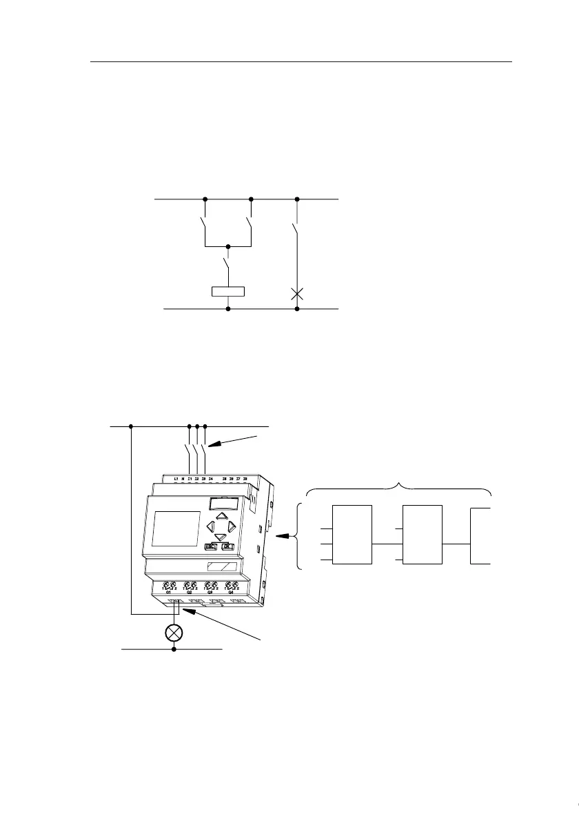
View of a circuit diagram
You know, of course, how a circuit logic is represented in a
circuit diagram. Nevertheless, here is an example:
Creating this circuit with IDEC SmartRelay
In IDEC SmartRelay you create a circuit logic by intercon-
necting blocks and connectors:
The load E1 is switched on
and off by means of the
switches (S1 OR S2) AND S3.
Relay K1 picks up when the
condition (S1 OR S2) AND S3
is met.
K1
S1
K1
S2
E1
S3
S1 ... S3
I3
x
Q1
&≥ 1
I1
I2
x
L
1
N
Wiring of the inputs
Circuit program in IDEC SmartRelay
Wiring of the outputs
Courtesy of Steven Engineering, Inc. ● 230 Ryan Way, South San Francisco, CA 94080-6370 ● General Inquiries: (800) 670-4183 ● www.stevenengineering.com