IDEC SmartRelay functions
IDEC SmartRelay Manual 161
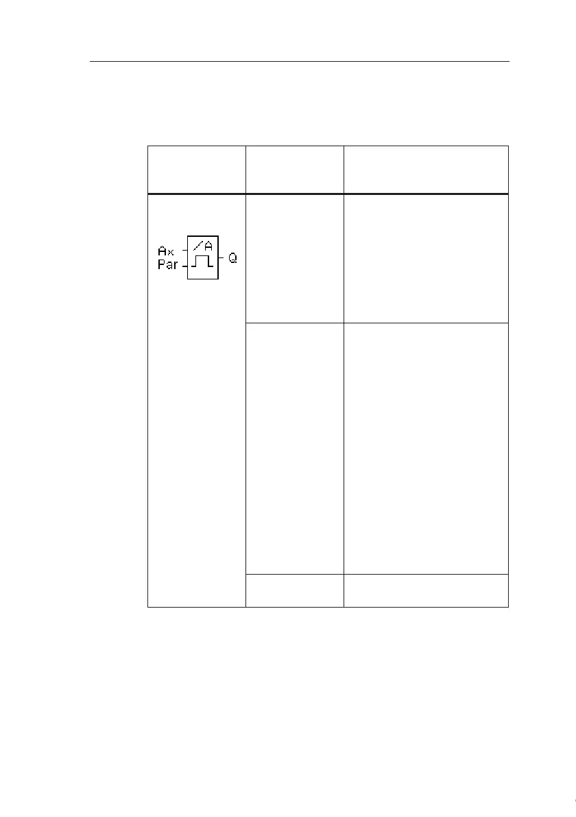
4.4.16 Analog trigger
Short description
The output is set and reset at two configurable thresholds.
* AI1...AI8:0...10 V corresponds with 0...1000 (internal val-
ue).
Symbol in
IDEC
SmartRelay
Wiring Description
Input Ax You apply the analog signal
to be analyzed at input Ax.
Use the analog inputs
AI1...AI8
(
*
)
, the Analog
Memory Markers
AM1...AM6, the block num-
ber of a function with analog
output.
Parameter A: Gain
Range of values:
00.00...10.00
B: Zero offset
Range of values:
±10.000
On: On threshold
Range of values:
±20.000
Off: Off threshold
Range of values:
±20.000
p: Number of decimals
Range of values:
0, 1, 2, 3
Output Q Q is set or reset by the
threshold triggers.
Courtesy of Steven Engineering, Inc. ● 230 Ryan Way, South San Francisco, CA 94080-6370 ● General Inquiries: (800) 670-4183 ● www.stevenengineering.com
 Loading...
