IDEC SmartRelay functions
128
IDEC SmartRelay Manual
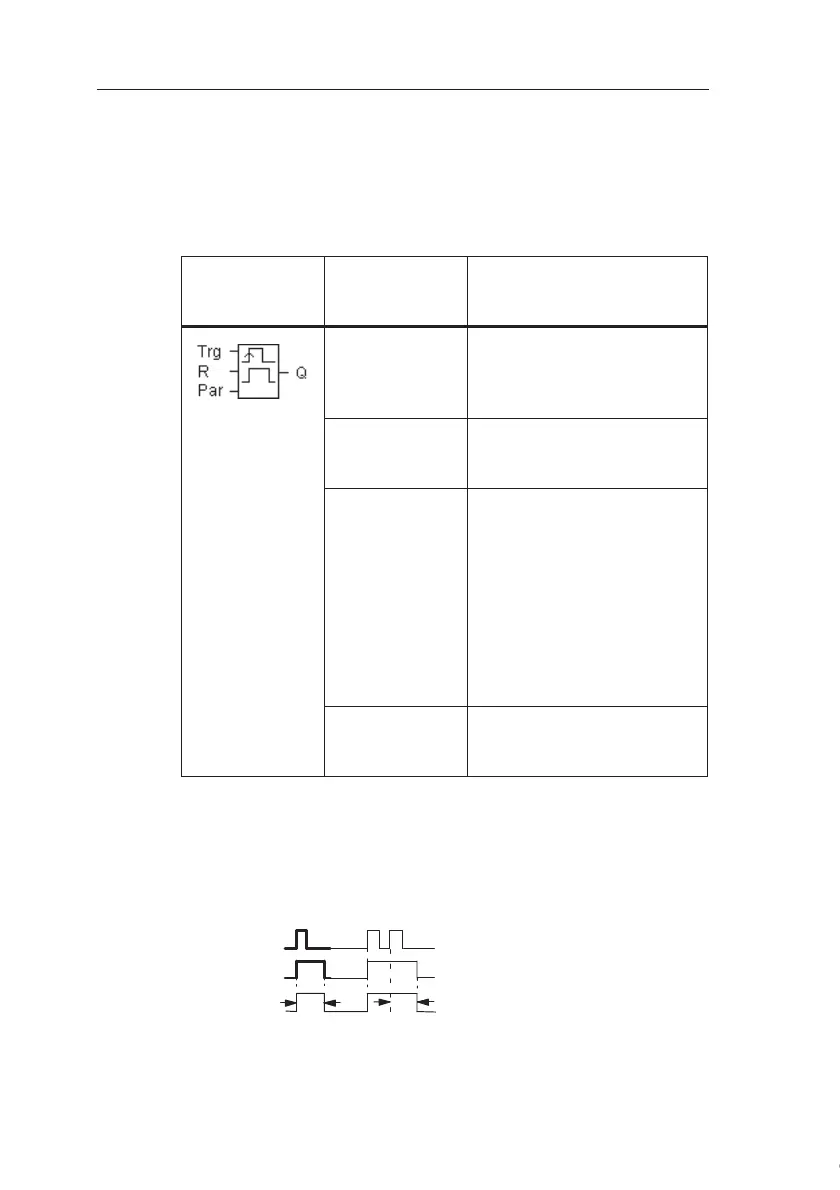
4.4.6 Edge-triggered interval time-delay relay
Short description
An input pulse generates a preset number of output pulses
with a defined pulse/pause ratio (retriggerable), after a con-
figured delay time has expired.
Parameter T
Please note the information on parameter T in Chapter
4.3.2.
Timing diagram A
Symbol in
IDEC
SmartRelay
Wiring Description
Input Trg A signal at input Trg (Trigger)
triggers the times for the
edge-triggered interval time-
delay relay.
Input R A signal at input R resets the
current time (T
a
) and the out-
put.
Parameter The interpulse width T
L
and
the pulse width T
H
are con-
figurable.
N determines the number of
pulse/pause cycles TL/TH:
Range of values: 1...9
Retentivity:
/ = No retentivity
R = The status is retentive.
Output Q Q is set after TL has expired,
and reset after TH has ex-
pired.
Trg
Q
T
H
T
H
N=1
T
L
=0
T
a
is
running
The bold section of the tim-
ing diagram also appears
in the symbol of the edge-
triggered interval time-de-
lay relay.
Courtesy of Steven Engineering, Inc. ● 230 Ryan Way, South San Francisco, CA 94080-6370 ● General Inquiries: (800) 670-4183 ● www.stevenengineering.com