IDEC SmartRelay functions
IDEC SmartRelay Manual 129
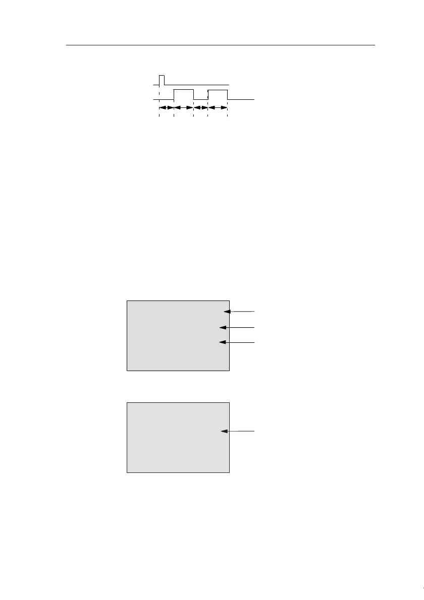
Timing diagram B
Functional description
A 0 to 1 transition at input Trg triggers the time T
L
(Time
Low). After the time T
L
has expired, output Q is set for the
duration of T
H
(Time High).
If there is a further 0 to 1 transition (retriggering pulse) at in-
put Trg before the preset time (T
L
+ T
H
) has expired, T
a
is
reset and the pulse/pause cycle is restarted.
If retentivity is not set, output Q and the time are reset after
a power failure.
Preset of the Par parameter
View in programming mode (example):
Press
Trg
N=2
Q
T
L
T
H
T
L
T
H
T
L
T
H
T
L
T
H
Timing diagram for the
sample configuration
B25 1+R
TL =02:00s
TH =03:00s
Protection mode and retentivity
Interpulse width
Pulse width
▲
B25 2
N=
1
Number of pulse/pause cycles
(example)
Courtesy of Steven Engineering, Inc. ● 230 Ryan Way, South San Francisco, CA 94080-6370 ● General Inquiries: (800) 670-4183 ● www.stevenengineering.com
 Loading...
