IDEC SmartRelay functions
178
IDEC SmartRelay Manual
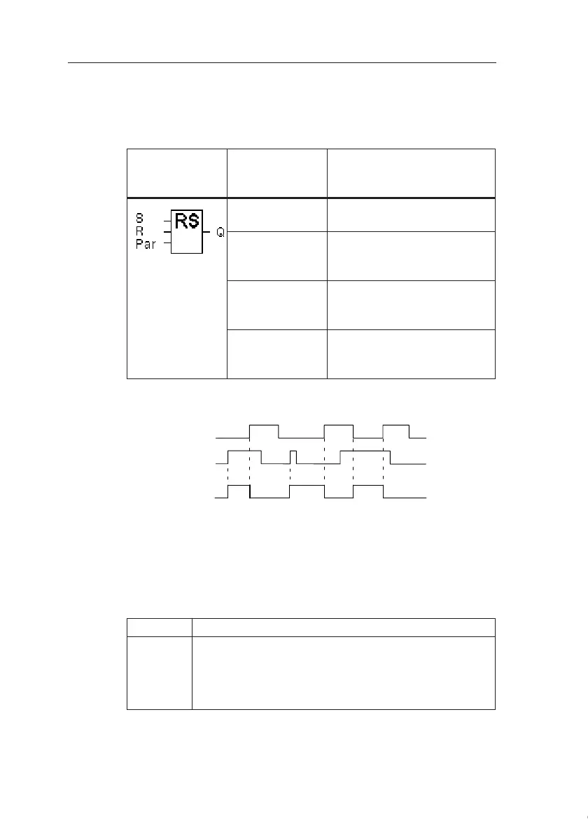
4.4.21 Latching relay
Short description
Input S sets output Q, input R resets output Q again.
Timing diagram
Switching response
A latching relay represents a simple binary element. The out-
put value depends on the status at the inputs and on the pre-
vious output status. The following table shows the logic once
again:
When retentivity is enabled, the current status of the output
signal is retained after a power failure.
Symbol in
IDEC
SmartRelay
Wiring Description
Input S You set output Q with a sig-
nal at input S.
Input R You reset output Q with a
signal at input R. If S and R
= 1, the output is reset.
Parameter Retentivity:
/ = No retentivity
R = The status is retentive.
Output Q Q is set with a signal at input
S, and reset with a signal at
input R.
S
n
R
n
Q Comment
00 xThe status is retentive
01 0Reset
10 1Set
11 0Reset (takes priority over Set)
Courtesy of Steven Engineering, Inc. ● 230 Ryan Way, South San Francisco, CA 94080-6370 ● General Inquiries: (800) 670-4183 ● www.stevenengineering.com