IDEC SmartRelay functions
IDEC SmartRelay Manual 193
4.4.25 Shift register
Short description
You can use the shift register function to read the value of an
input and to shift its bits left or right. The output value corre-
sponds with the configured shift register bit. The shifting di-
rection can be changed at a special input.
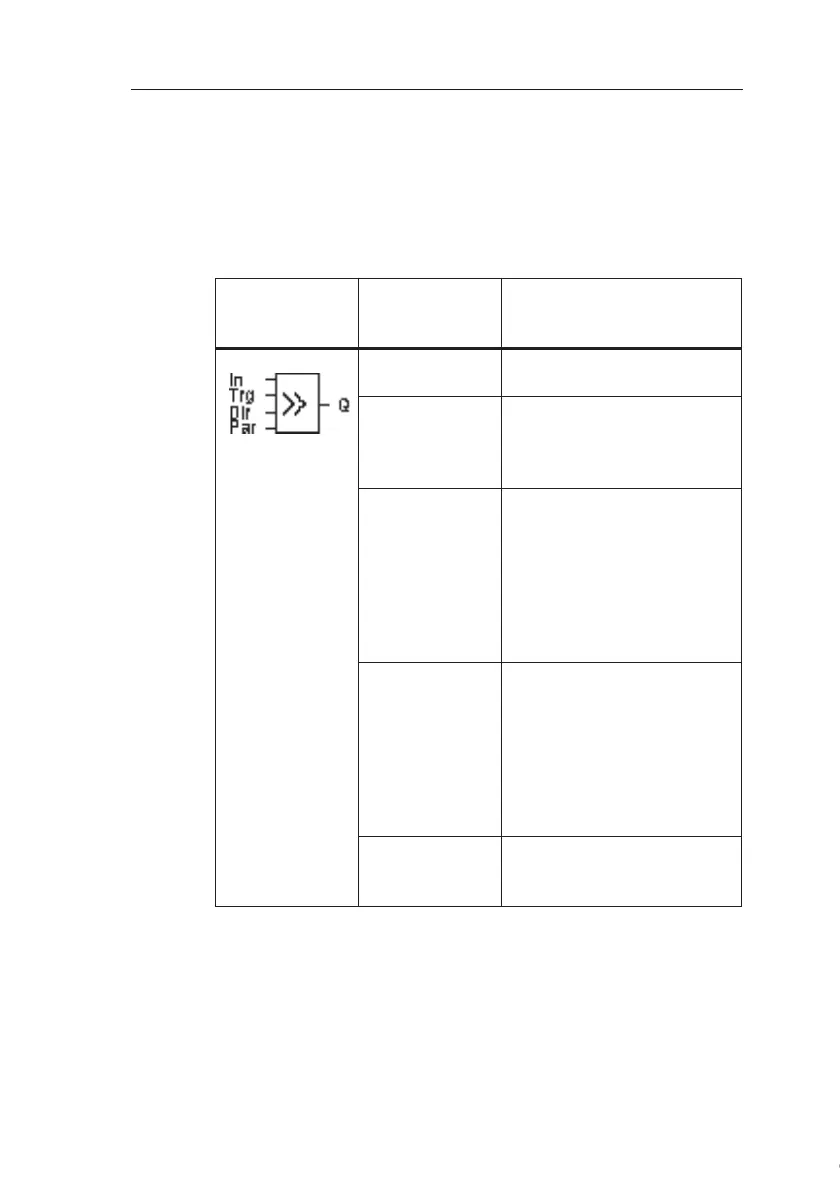
Symbol in
IDEC
SmartRelay
Wiring Description
Input In Input read at the start of the
function.
Input Trg A positive edge (0 to 1 transi-
tion) at input Trg (Trigger)
starts the special function. 1
to 0 transitions are irrelevant.
Input Dir The signal at input Dir deter-
mines the shifting direction
for the shift register bits
S1...S8 an:
Dir = 0: Shift up (S1 >> S8)
Dir = 1: Shift down (S8 >>
S1)
Parameter
Shift register bit that deter-
mines the value at output Q.
Possible settings:
S1 ... S8
Retentivity:
/ = No retentivity
R = The status is retentive.
Output Q The output value corre-
sponds with the configured
shift register bit.
Courtesy of Steven Engineering, Inc. ● 230 Ryan Way, South San Francisco, CA 94080-6370 ● General Inquiries: (800) 670-4183 ● www.stevenengineering.com