IDEC SmartRelay functions
194
IDEC SmartRelay Manual
Functional description
The function reads the value at input In with a positive edge
(0 to 1 transition) at input Trg (Trigger).
This value is applied to shift register bit S1 or S8, depending
on the shifting direction:
• Shift up: The value at input In is set at S1; the previous
value at S1 is shifted to S2; the previous value at S2 is
shifted to S3 etc.
• Shift down: The value at input In is set at S8; the previous
value at S8 is shifted to S7; the previous value at S7 is
shifted to S6 etc.
Output Q returns the value of the configured shift register bit.
If retentivity is disabled, the shift function restarts at S1 or S8
after a power failure. When enabled, retentivity always ap-
plies to all shift register bits.
Note
The special function shift register can be used only once in the cir-
cuit program.
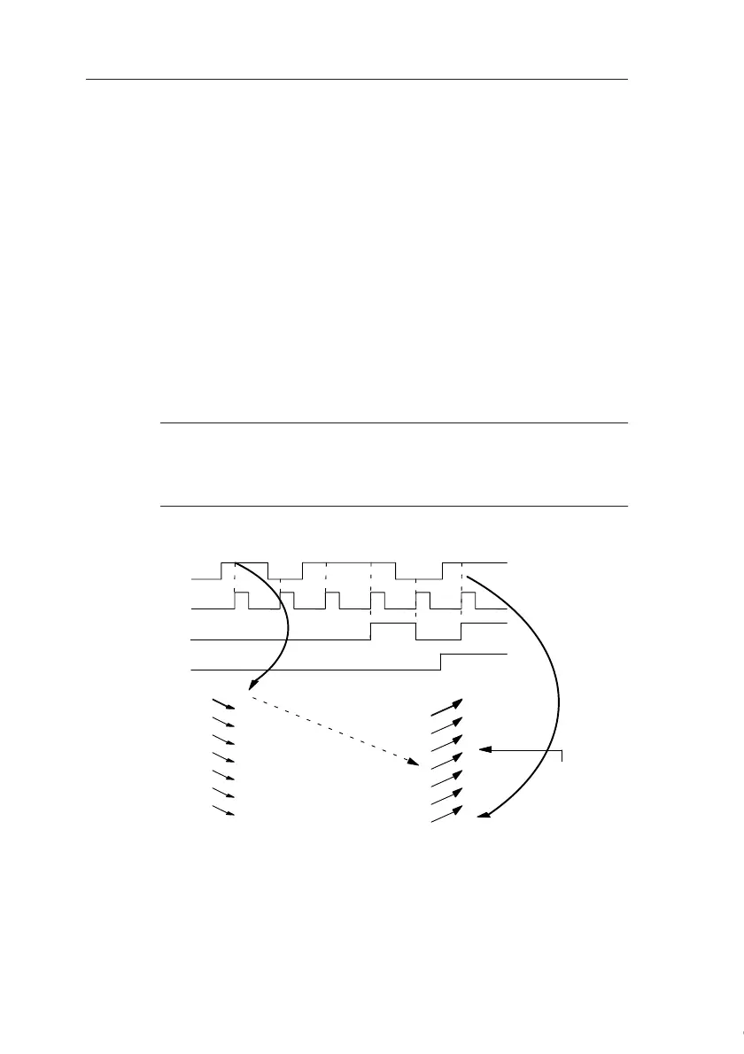
Timing diagram
Trg
In
Q
Dir
S1
1011
01
S2
0101
11
S3
0010
10
S4
0001
01
S5
0000
10
S6
1000
00
S7
1100
00
S8
0110
01
0
0
0
0
1
1
0
0
Shift up Shift down
S4 = Q
(example)
Courtesy of Steven Engineering, Inc. ● 230 Ryan Way, South San Francisco, CA 94080-6370 ● General Inquiries: (800) 670-4183 ● www.stevenengineering.com
 Loading...
