IDEC SmartRelay functions
IDEC SmartRelay Manual 125
Select the required function by means of the block number.
The timebase is configurable. For information on valid rang-
es and parameter defaults, refer to Chapter 4.4.1.
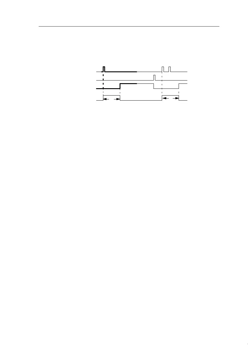
Timing diagram
Functional description
The 0 to 1 signal transition at input Trg triggers the current
time T
a
. Output Q is set when T
a
= T. A further signal at input
Trg does not influence the time T
a
.
The output and the time T
a
are reset with the next 1 signal at
input R.
If retentivity is not set, output Q and the expired time are re-
set after a power failure.
Trg
T
Q
R
T
T
a
expires
The bold section of the timing diagram is also shown in the symbol
of the retentive on-delay.
Courtesy of Steven Engineering, Inc. ● 230 Ryan Way, South San Francisco, CA 94080-6370 ● General Inquiries: (800) 670-4183 ● www.stevenengineering.com
 Loading...
