Getting started with IDEC SmartRelay
4
IDEC SmartRelay Manual
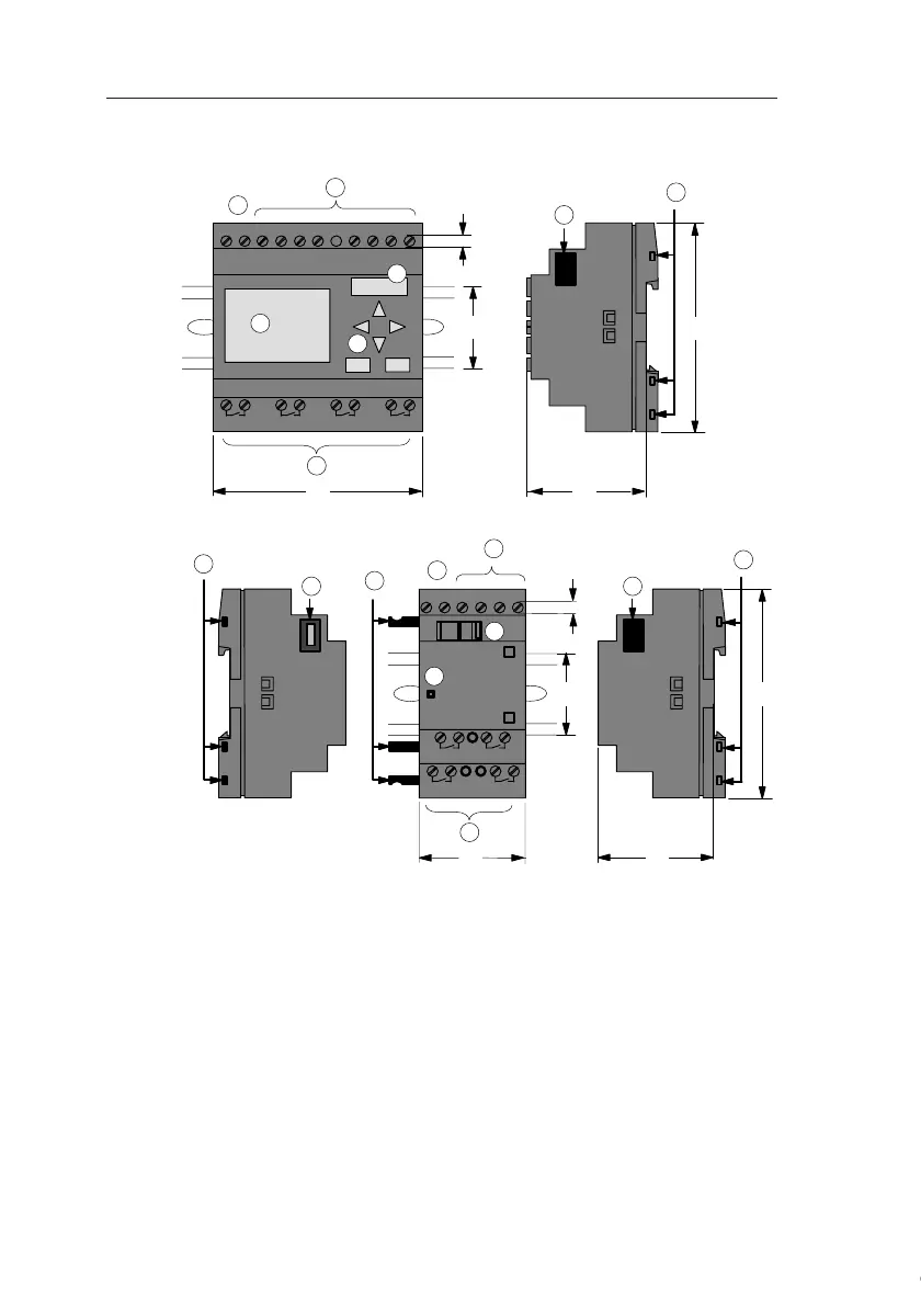
The IDEC SmartRelay structure
1. Power supply 5. Control panel
(not with FL1C-B12...)
8. Expansion interface
2. Inputs 6. LCD
(not with FL1C-B12...)
9. Mechanical coding
pins
3. Outputs 7. RUN/STOP indicator 10. Mechanical coding
sockets
4. Module slot with cap 11. Slide
1
2
3
I7 I8
Q1 Q2 Q3 Q4
4
35
72
L1 N
4
90
55
I5 I6I2 I3 I4I1
Q4
Q1 Q2
35
L1 N I2 I3 I4I1
36
RUN/STOP
90
53
3
1
2
9
9
10
8
88
10
11
1 2 1 2 1 2 1 2
1 2 1 2
1 2 1 2
5
6
7
4
Q3
IDEC SmartRelay Basic
(e.g.: FL1C-H12RCC)
IDEC SmartRelay
expansion module
(e.g.: FL1B-M08C2R2)
Courtesy of Steven Engineering, Inc. ● 230 Ryan Way, South San Francisco, CA 94080-6370 ● General Inquiries: (800) 670-4183 ● www.stevenengineering.com
 Loading...
