Applications
IDEC SmartRelay Manual 229
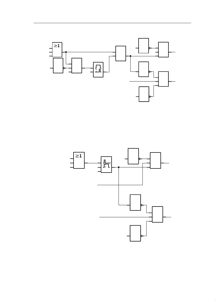
Door control system with IDEC SmartRelaycircuit diagram
This is what the circuit diagram of the conventional solution
looks like.
You can simplify this circuit if you make use of the IDEC
SmartRelay functions. You can use the off-delay function to
replace the latching relay and the on-delay. The block dia-
gram below illustrates this simplification:
&
1
1
1
&
I4
I3
Q2
Q1
RS
I1
I2
1
I4
T=
4s
x
&
x
Q1
Q2
Open
Close
&
1
1
1
&
I4
I3
I1
I2
x
Q2
Q1
x
10 s
Q1
Q2
Open
CloseClose
Motion
detector
Limit switch
Door open
Limit switch
Door closed
Courtesy of Steven Engineering, Inc. ● 230 Ryan Way, South San Francisco, CA 94080-6370 ● General Inquiries: (800) 670-4183 ● www.stevenengineering.com
 Loading...
