Applications
240
IDEC SmartRelay Manual
Components used
•K1 contactor relay
•K2 contactor relay
•S0 (break contact) STOP pushbutton
•S1 (make contact) OPEN pushbutton
•S2 (make contact) CLOSE pushbutton
•S3 (break contact) Position sensor OPEN
•S4 (break contact) Position sensor CLOSED
•S5 (break contact) Safety bar
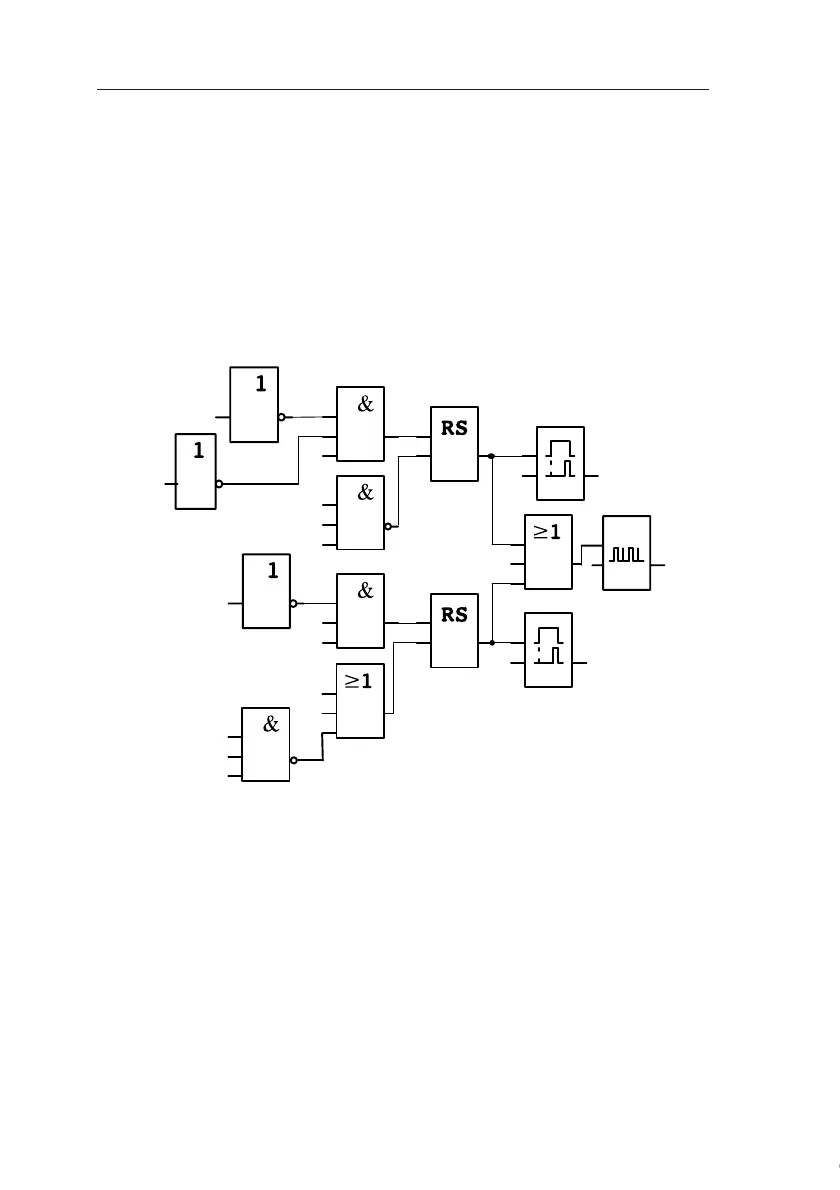
Block diagram of the IDEC SmartRelay solution
The OPEN or CLOSE pushbuttons initiate the gate motion,
provided it is not already moving in the other direction. The
gate is stopped by means of the STOP pushbutton or the rel-
evant limit switch. A safety bar furthermore interrupts the
closing motion of the gate.
T=
5 s
T=
5 s
x
x
x
x
Q1
Q3
Q2
I3
I4
I3
I6
I5
I1
I2
Q2
Q1
T
H
=
T
L
=2 s
Inv=lo
I2
I1
Start push-
button
CLOSED
Start push-
button OPEN
STOP push-
button
Gate is open
CLOSE push-
button
CLOSE pushbutton
OPEN pushbutton
STOP pushbutton
Safety bar
Gate is closed
Open
Signal
lamp
Close
Courtesy of Steven Engineering, Inc. ● 230 Ryan Way, South San Francisco, CA 94080-6370 ● General Inquiries: (800) 670-4183 ● www.stevenengineering.com
 Loading...
