Applications
IDEC SmartRelay Manual 249
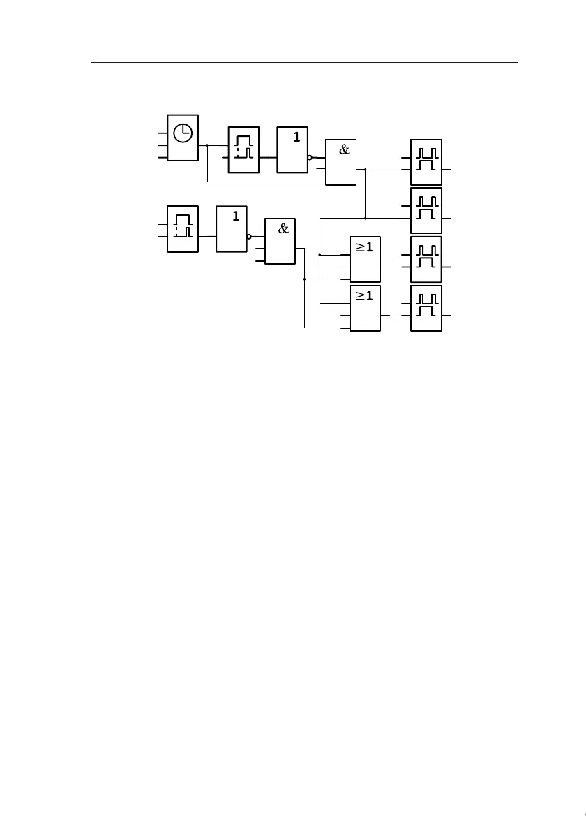
Block diagram of the IDEC SmartRelay solution
Advantages of the IDEC SmartRelay solution
• You can connect the lamps directly to the IDEC SmartRe-
lay, provided the power consumption does not exceed
the switching capacity of the various outputs. Higher
loads should be switched with a contactor relay.
• Connect the daylight control switch directly to an input of
the IDEC SmartRelay.
• You do not need an external timer, because this function
is integrated in the IDEC SmartRelay.
• Due to the reduced amount of switchgear, you can install
a smaller and space-saving distribution cabinet.
• Fewer devices are required
• The lighting system can be easily modified.
• Additional switching times can be set as required (se-
quential circuit for the off pulses at the end of the day).
• The function of the daylight control switch can be easily
applied to all lamps or to a modified group of lamps.
x
T=
1s
I5
T=
1s
x
I5
I1
I2
I3
I4
x
x
Off pulse triggered with timer
Mo..Su
20:00 -- 20.01
Mo..Su
21:00 -- 21.01
Off pulse triggered with daylight control switch
Daylight
control
switch
Luminous row 3
Corridor side
Q3
Luminous row
4 Corridor side
Q4
Luminous row 1
Corridor side
Q1
Luminous row 2
Corridor side
Q2
Courtesy of Steven Engineering, Inc. ● 230 Ryan Way, South San Francisco, CA 94080-6370 ● General Inquiries: (800) 670-4183 ● www.stevenengineering.com