Determining the cycle time
IDEC SmartRelay Manual 273
3. Now start the circuit program and switch IDEC SmartRe-
lay to parameter assignment mode. In this mode, view
the trigger parameters.
4. The reciprocal value of f
a
is equivalent to the IDEC
SmartRelay execution time of the current circuit program
in its memory.
1/f
a
= cycle time in s
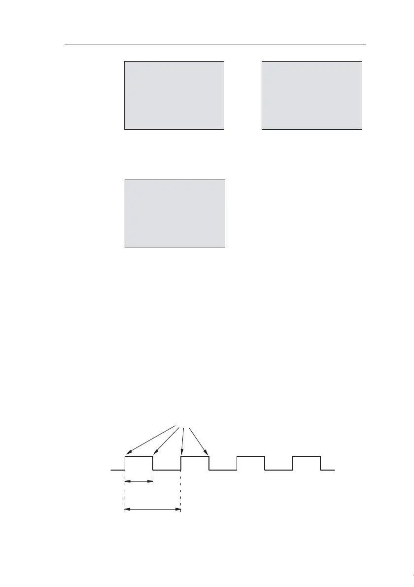
Explanation
The inverted marker block changes its output signal at each
program execution. Thus, one logic level (high or low) width
is exactly equivalent to the length of one cycle. Hence, a pe-
riod lasts 2 cycles.
The frequency trigger indicates the ratio of periods per 2 sec-
onds, which results in the ratio of cycles per second.
B1 1+
On =1000
Off=0000
B1 2
G_T=02:00s
Press
▲
B1
On =1000
Off =0000
fa =0086
f
a
= total of measured pulses per
timeba
1 period = 1 pulse = 2 cycles
Period
Cycle
time
Edge transition of the inverted marker
at each circuit program execution
Courtesy of Steven Engineering, Inc. ● 230 Ryan Way, South San Francisco, CA 94080-6370 ● General Inquiries: (800) 670-4183 ● www.stevenengineering.com