Programming IDEC SmartRelay
IDEC SmartRelay Manual 45
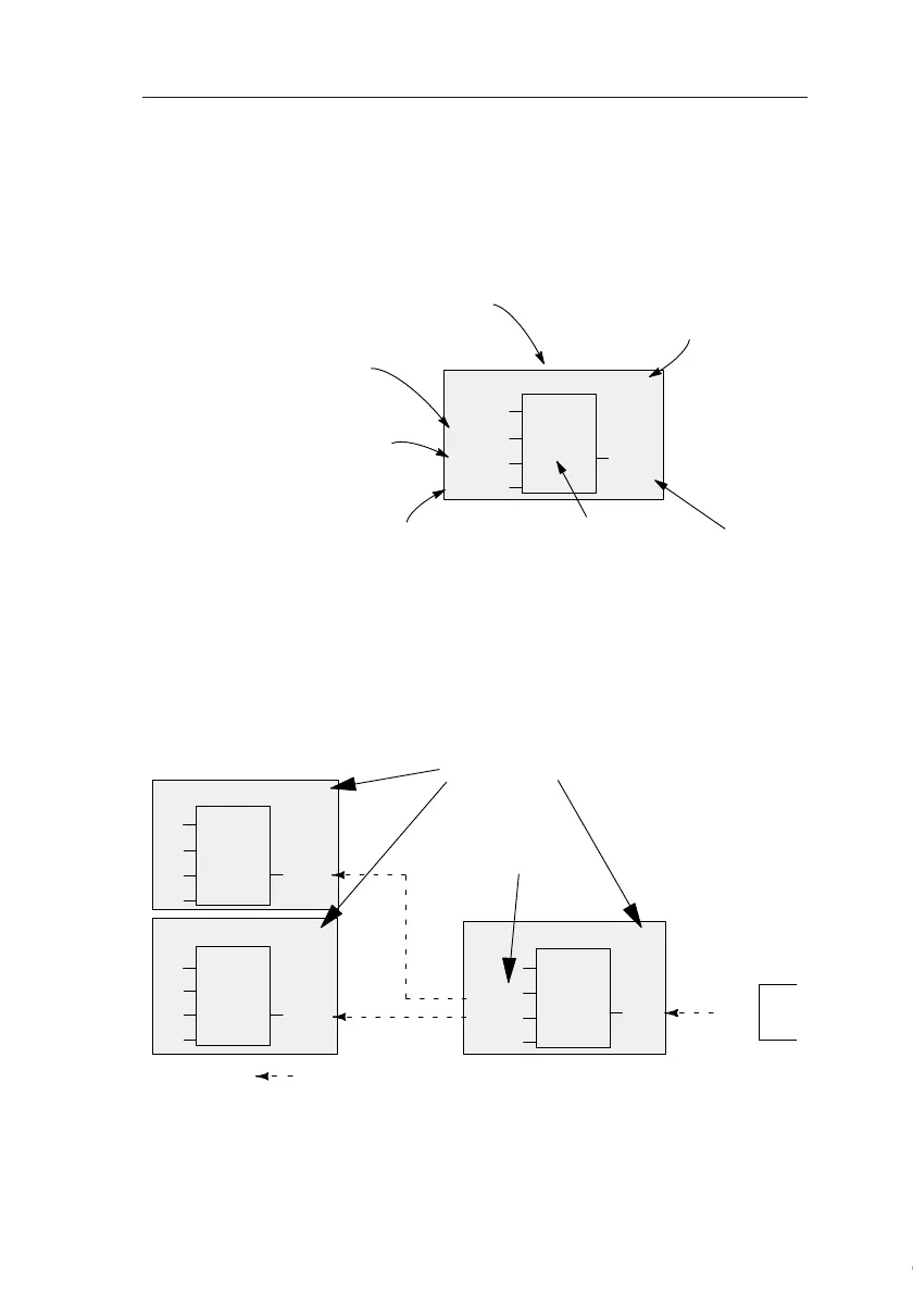
View of blocks on the IDEC SmartRelay display
The figure below shows a typical view of the IDEC SmartRe-
lay display. As you can see, it can show only one block at a
time. We have therefore introduced block numbers to help
you check the circuit structure.
Assigning a block number
IDEC SmartRelay assigns each new block a circuit program
a block number.
IDEC SmartRelay uses these block numbers to indicate the
block interconnections. Hence, these numbers primarily rep-
resent a help for your orientation in the circuit program.
≥ 1
B2
I3
Q1
B1
x
x
View of the IDEC Smart-
Relay display
A further block is
connected at this
point
Input
This connector is not required
Block
Output
Block number as-
signed by IDEC
SmartRelay
I1
I2
I3
≥ 1
B1
B2
B2
≥ 1
B3
Q1
B1
B1
I4
I5
I6
≥ 1
B1
Q1
x
B3
x
x
x
Block numbers
These blocks are
interconnected
Scrolling the circuit program using the key
▲
Courtesy of Steven Engineering, Inc. ● 230 Ryan Way, South San Francisco, CA 94080-6370 ● General Inquiries: (800) 670-4183 ● www.stevenengineering.com