Page XII
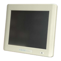
POC-3174B-A330 Medical Panel PC
List of Figures
Figure 1-1: POC-3174B-A330 Medical Panel PC ........................................................2
Figure 1-2: Front View...................................................................................................4
Figure 1-3: Rear View....................................................................................................5
Figure 1-4: Bottom View...............................................................................................6
Figure 1-5: Left View.....................................................................................................7
Figure 2-1: POC-3174B-A330 Dimensions (units in mm)........................................11
Figure 2-2: Memory Module and Memory Socket ....................................................12
Figure 2-3: COM Ports ................................................................................................14
Figure 2-4: RJ-45 Ethernet Connectors ....................................................................14
Figure 2-5: RJ-45 Remote Control Connector..........................................................15
Figure 2-6: External USB Ports..................................................................................16
Figure 2-7: LCD Screen ..............................................................................................16
Figure 2-8: VGA and DVI Connectors........................................................................17
Figure 2-9: Audio Jacks..............................................................................................18
Figure 2-10: Stereo Speakers.....................................................................................18
Figure 2-11: Power Connector...................................................................................19
Figure 2-12: Lithium Battery Pack.............................................................................20
Figure 2-13: AT/ATX Mode Switch.............................................................................20
Figure 2-14: UPS/Battery Mode Switch.....................................................................21
Figure 2-15: Wireless LAN Module and PIFA Antennas..........................................23
Figure 4-1: Back Cover Retention Screws................................................................30
Figure 4-2: Connect the Battery.................................................................................31
Figure 4-3: PCI Card Installation................................................................................32
Figure 4-4: CF Slot Cover Retention Screws............................................................32
Figure 4-5: CF Card Installation.................................................................................33
Figure 4-6: AT/ATX Switch Location .........................................................................33
Figure 4-7: Wall-mounting Bracket............................................................................35
Figure 4-8: Chassis Support Screws.........................................................................36
 Loading...