Page 38
POC-3174B-A330 Medical Panel PC
Step 2: Once the mounting arm has been firmly attached to the surface, lift the flat panel
PC onto the interface pad of the mounting arm.
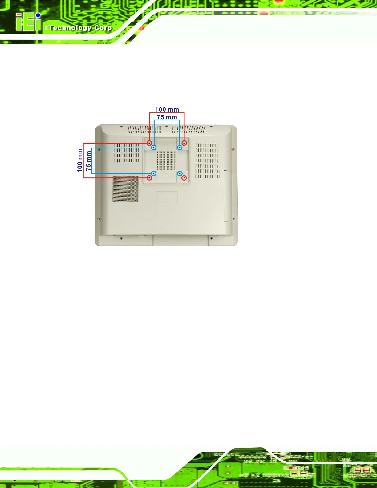
Step 3: Align the retention screw holes on the mounting arm interface with those in the
flat panel PC, as shown in
Figure 4-10.
Figure 4-10: Arm Mounting Retention Screw Holes
Step 4: Secure the flat panel PC to the interface pad by inserting four retention screws
through the bottom of the mounting arm interface pad and into the flat panel PC.
Step 0:
4.10 Bottom Panel Connectors
All the external peripheral interface connectors are located at the bottom of the rear panel
on the POC-3174B-A330 medical panel PC.
4.10.1 Audio Connection
Audio signals are interfaced through three phone jack connections. The pink phone jack is
for Mic In and green is for Speaker Out. Follow the steps below to connect audio devices
to the POC-3174B-A330.
 Loading...