Page 39
POC-3174B-A330 Medical Panel PC
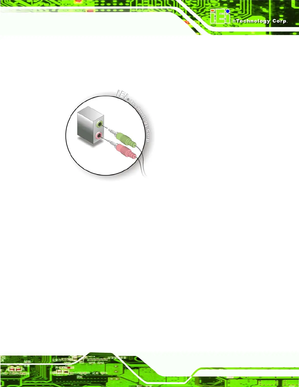
Step 1: Locate the audio phone jacks. The locations of the audio phone jacks are
shown in Chapter 3.
Step 2: Insert audio phone jack plugs. Insert audio phone jack plugs into the audio
phone jacks on the external peripheral interface. See
Figure 4-11. Step 0:
Figure 4-11: Audio Connectors
4.10.2 DVI Display Device Connection
The POC-3174B-A330 has a single female DVI-I connector on the bottom panel. The
DVI-I connector is connected to a digital display device. To connect a digital display device
to the POC-3174B-A330, please follow the instructions below.
Step 1: Locate the DVI-I connector. The location of the DVI-I connector is shown in
Chapter 2.
Step 2: Align the DVI-I connector. Align the male DVI-I connector on the digital display
device cable with the female DVI-I connector on the external peripheral
interface.
Step 3: Insert the DVI-I connector. Once the connectors are properly aligned with the
male connector, insert the male connector from the digital display device into the
female connector on the POC-3174B-A330. See
Figure 4-12.
 Loading...