Home
IEI Technology
Desktop
POC-3174B-A330
IEI Technology POC-3174B-A330 User Manual
4
of 1
of 1 rating
185 pages
Give review
Manual
Specs
To Next Page
To Next Page
To Previous Page
To Previous Page
Loading...
Page 1
14
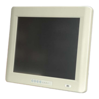
POC-3174B-A330 Medical Panel PC
Figure 7-21: InstallShield Wizard Welcome Screen
Step 5:
Click
N
EXT
to continue the inst
allation.
Step 6:
InstallShield st
arts to inst
all the new software as
shown in
Figure 7-22
.
Figure 7-22: Audio Driver Soft
w
are Configura
tion
Step 7:
The Installation Wi
zard updates the system as shown in
Figure 7-23
.
129
131
Table of Contents
Table of Contents
7
Default Chapter
4
Manual Conventions
4
1 Introduction
17
General Overview
18
Figure 1-1: POC-3174B-A330 Medical Panel PC
18
Features and Model Variation
19
External Overview
19
Front Panel
19
Figure 1-2: Front View
20
Bottom Panel
21
Table 1-1: LCD Front Controls
21
Figure 1-3: Rear View
21
Rear Panel
21
Figure 1-4: Bottom View
22
Side Panel
22
Specifications
23
Preinstalled Hardware Components
23
System Specifications
23
Figure 1-5: Left View
23
Table 1-2: System Specifications
25
2 Specifications
26
Dimensions
27
Figure 2-1: POC-3174B-A330 Dimensions (Units in MM)
27
Intel® Processor Support
28
Motherboard Components
28
Installed Memory
28
Memory Support
28
Storage Capacity
29
Figure 2-2: Memory Module and Memory Socket
28
Additional Memory
29
External Peripheral Interface Connectors
29
Serial Port Connectors
29
LAN Connectivity
30
Figure 2-3: COM Ports
30
Figure 2-4: RJ-45 Ethernet Connectors
30
External USB Connectors
31
Figure 2-5: RJ-45 Remote Control Connector
31
LAN Connector for Remote Control
31
Poc-3174B-A330 Front Side
32
Monitor
32
Figure 2-6: External USB Ports
32
Figure 2-7: LCD Screen
32
Audio
33
High Definition Audio Controller
33
Figure 2-8: VGA and DVI Connectors
33
Graphics
33
Dual-Display
33
Intel ® 915GME Integrated Graphics Media Accelerator 900
33
Touch-Screen Module
33
Stereo Speakers
34
System Power
34
Power Adapter
34
Figure 2-9: Audio Jacks
34
Figure 2-10: Stereo Speakers
34
Figure 2-11: Power Connector
35
Lithium Battery
35
Power Connector
35
Figure 2-12: Lithium Battery Pack
36
Figure 2-13: AT/ATX Mode Switch
36
Power Mode
36
Figure 2-14: Ups/Battery Mode Switch
37
Power On/Off
38
Table 2-1: Power Modes (Turning on the System)
38
Table 2-2: Power Modes (Turning off the System)
38
Figure 2-15: Wireless LAN Module and PIFA Antennas
39
Wireless Ethernet Connections
39
3 Unpacking
40
Npacking
41
Packing List
42
4 Installation
43
Anti-Static Precautions
44
Installation Precautions
44
Installation and Configuration Steps
45
Plastic Back Cover Removal
45
Connect the Battery
46
Figure 4-1: Back Cover Retention Screws
46
Pci Expansion Card Installation
47
Figure 4-2: Connect the Battery
47
Cf Card Installation
48
Figure 4-3: PCI Card Installation
48
Figure 4-4: CF Slot Cover Retention Screws
48
At/Atx Mode Selection
49
Figure 4-5: CF Card Installation
49
Figure 4-6: AT/ATX Switch Location
49
Mounting the System
50
Wall Mounting
50
Figure 4-7: Wall-Mounting Bracket
51
Figure 4-8: Chassis Support Screws
52
Arm Mounting
53
Figure 4-9: Secure the Panel PC
53
Bottom Panel Connectors
54
Audio Connection
54
Figure 4-10: Arm Mounting Retention Screw Holes
54
DVI Display Device Connection
55
Figure 4-11: Audio Connectors
55
LAN Connection
56
Figure 4-12: DVI Connector
56
PS/2 Keyboard and Mouse Connection
57
Figure 4-13: LAN Connection
57
Serial Device Connection
58
Figure 4-14: PS/2 Keyboard/Mouse Connector
58
USB Device Connection
59
Figure 4-15: Serial Device Connector
59
VGA Monitor Connection
60
Figure 4-16: USB Device Connection
60
Figure 4-17: VGA Connector
61
5 System Maintenance
62
Introduction
63
Motherboard Replacement
63
Plastic Back Cover Removal
63
Figure 5-1: Back Cover Retention Screws
64
Hdd Replacement
65
Figure 5-2: Wall Mount Bracket Retention Screws
65
Memory Module Replacement
66
Figure 5-3: Hard Drive Retention Screws
66
Figure 5-4: Platform Retention Screws
67
Figure 5-5: SO-DIMM Socket Locations
67
Figure 5-6: DDR2 SO-DIMM Module Installation
68
Jumper Settings
69
COM Port Voltage Select (J4)
69
Table 5-1: COM Port Voltage Settings
70
Compactflash® Setup (J9)
71
Figure 5-7: COM Port Voltage Select Jumper Location
70
Table 5-2: Compactflash® Master/Slave Selection
71
Figure 5-8: COM Port Voltage Select Jumper Location
71
6 Ami Bios Setup
72
Introduction
73
Starting Setup
73
Using Setup
73
BIOS Menu Bar
74
Getting Help
74
Unable to Reboot after Configuration Changes
74
Table 6-1: BIOS Navigation Keys
74
Main
75
Menu 1: Main
75
System Overview
75
Advanced
76
System Date [XX/XX/XX]
76
System Time [XX:XX:XX]
76
CPU Configuration
77
Menu 2: Advanced
77
Menu 3: CPU Configuration
77
IDE Configuration
78
Menu 4: IDE Configuration
78
ATA/IDE Configurations [Compatible]
78
IDE Master and IDE Slave
79
Legacy IDE Channels [SATA Pri., PATA Sec]
79
IDE Master, IDE Slave
80
Menu 5: IDE Master and IDE Slave Configuration
80
Type [Auto]
80
Block (Multi Sector Transfer) [Auto]
81
Lba/Large Mode [Auto]
81
Zip
81
DMA Mode [Auto]
82
PIO Mode [Auto]
82
32Bit Data Transfer [Enabled]
84
Auto]
84
Super IO Configuration
85
Menu 6: Super IO Configuration
85
Serial Port1 Address [3F8/IRQ4]
85
Serial Port1 Mode [Normal]
86
Serial Port2 Address [2F8/IRQ3]
86
Serial Port2 Mode [Normal]
86
Serial Port3 Address [3E8]
87
Serial Port3 IRQ [10]
87
Serial Port3 Mode [RS232]
87
Touch Panel Address [2E8]
87
Serial Port5 Address [2F0]
88
Serial Port5 IRQ [10]
88
Touch Panel IRQ [10]
88
Serial Port6 Address [2E0]
89
Serial Port6 IRQ [10]
89
Hardware Health Configuration
90
Menu 7: Hardware Health Configuration
90
CPU FAN Mode Setting [Automatic Mode]
90
SYS FAN Mode Setting [Full on Mode]
91
Temp. Limit of off
91
Fan Start PWM
92
Temp. Limit of Start
92
Slope PWM 1
93
ACPI Configuration
94
Menu 8: ACPI Configuration
94
Suspend Mode [S1 (POS)]
94
Remote Access Configuration
95
Menu 9: Remote Access Configuration [Advanced]
95
Remote Access [Disabled]
95
Base Address, IRQ [3F8H,4]
96
Redirection after BIOS POST
96
Serial Port Mode
96
Serial Port Mode [115200 8,N,1]
96
Serial Port Number
96
Serial Port Number [COM1]
96
Terminal Type
96
Redirection after BIOS POST [Always]
97
Terminal Type [ANSI]
97
USB Configuration
98
Menu 10: USB Configuration
98
USB 2.0 Controller [Enabled]
98
USB Functions [Enabled]
98
Pci/Pnp
99
Legacy USB Support [Enabled]
99
USB2.0 Controller Mode [Hispeed]
99
Menu 11: Pci/Pnp Configuration
100
IRQ# [Available]
100
DMA Channel# [Available]
101
Boot
102
Menu 12: Boot
102
Boot Settings Configuration
103
Menu 13: Boot Settings Configuration
103
Quick Boot [Enabled]
103
Quiet Boot [Enabled]
103
Addon ROM Display Mode [Force BIOS]
104
Boot from LAN Support [Disabled]
104
Bootup Num-Lock [On]
104
Boot Device Priority
105
CD/DVD Drives
105
Hard Disk Drives
105
Menu 14: Security
106
Change Supervisor Password
106
Security
106
Chipset
107
Change User Password
107
Menu 15: Chipset
107
North Bridge Configuration
108
Menu 16:North Bridge Chipset Configuration
108
Memory Hole [Disabled]
108
Boot Display Device [Auto]
109
Flat Panel Type
109
Internal Graphics Mode Select [Enable, 8MB]
109
South Bridge Configuration
110
Menu 17:South Bridge Chipset Configuration
110
Spread Spectrum Function [Disabled]
110
Power Configuration
111
Menu 18: Power Configuration
111
Advanced Power Configuration
112
Menu 19: Advanced Power Configuration
112
Power Button Mode [On/Off]
112
RTC Resume [Disabled]
112
PME Resume [Disabled]
113
RI Resume [Disabled]
113
RTC Alarm Date (Days)
113
RTC Alarm Time
113
Keyboard/Mouse Resume [Disabled]
114
Exit
115
Menu 20:Exit
115
Discard Changes
115
Discard Changes and Exit
115
Save Changes and Exit
115
Load Failsafe Defaults
116
Load Optimal Defaults
116
7 Software Drivers
117
Available Software Drivers
118
Intel® Chipset Driver
118
Figure 7-1: Intel® Package Manager
119
Figure 7-2: Intel® Setup Welcome Screen
119
Figure 7-3: Intel® Chipset Driver License Agreement
120
Figure 7-4: Readme File
120
Intel® Graphics Media Accelerator Driver
121
Figure 7-5: Intel® Chipset Driver Complete Installation Screen
121
Figure 7-6: GMA Driver Readme File
122
Figure 7-7: GMA Driver File Extraction
122
Figure 7-8: GMA Driver Installation Welcome Screen
123
Figure 7-9: GMA Driver License Agreement
123
Realtek RTL8111CP Gbe LAN Installation
124
Figure 7-10: GMA Driver Installing Notice
124
Figure 7-11: GMA Driver Installation Complete
124
Figure 7-12: RTL8111CP Installshield Wizard
125
Figure 7-13: RTL8111CP Installshield Wizard Continues
125
Figure 7-14: RTL8111CP Installshield Wizard Welcome Screen
126
Figure 7-15: RTL8111CP Driver Ready Screen
126
Figure 7-16: RTL8111CP Drivers Installing
127
Figure 7-17: RTL8111CP Installshield Wizard
127
Realtek Hd Audio Driver Installation
128
BIOS Setup
128
Driver Installation
128
Figure 7-18: RTL8111CP Driver Installation Complete
128
Figure 7-19: the Installshield Wizard Starts
129
Figure 7-20: Preparing Setup Screen
129
Figure 7-21: Installshield Wizard Welcome Screen
130
Figure 7-22: Audio Driver Software Configuration
130
Figure 7-23: Installation Wizard Updates the System
131
Figure 7-24: Restart the Computer
131
Figure 7-25: Welcome Screen
132
Touch Screen Driver
132
Figure 7-26: License Agreement
133
Figure 7-27: Ready to Install the Program
133
Figure 7-28: Installing Penmount DMC9000
134
Figure 7-29: Reboot the Computer
134
Wireless Lan Driver
134
Figure 7-30: Windows Control Panel
135
Figure 7-31: System Icon
136
Figure 7-32: Device Manager Tab
137
Figure 7-33: Device Manager List
138
Figure 7-34: Search for Suitable Driver
139
Figure 7-35: Locate Driver Files
139
Figure 7-36: Location Browsing Window
140
8 Battery Monitoring and Remote Control
141
Introduction
142
Monitoring DC Power and Smart Battery
142
Application Installation
142
Figure 8-1: Welcome Screen
142
Figure 8-2: Select Installation Folder
143
Figure 8-3: Ready to Install the Program
143
Figure 8-4: Installing AUPS
144
Figure 8-5: Installation Complete
144
Figure 8-6: AUPS Battery Status Monitor Application
144
Status Information
145
DC Detection
145
Figure 8-7: Status Information
145
Figure 8-8: DC Detection
145
Battery Detection
146
Figure 8-9: Battery Detection
146
Battery Information
147
Figure 8-10: Total Battery Time
147
Figure 8-11: Battery Information
147
Total Battery Time
147
Figure 8-12: LAN Setting
148
LAN Setting
148
Figure 8-13: LAN Setting - Change Password
149
Setting
149
Figure 8-14: Application Setting
150
Figure 8-15: COM Port Status
150
Figure 8-16: RJ-45 Remote LAN Connector
151
Remote Control and Monitoring
151
Figure 8-17: IEI REMOTE AP
152
Figure 8-18: IEI REMOTE AP - IP Address
153
Figure 8-19: Remote Management Web Interface - Status
153
Figure 8-20: Remote Management Web Interface - Send Email
154
Figure 8-21: Enter User Name and Password
154
Figure 8-22: Board Configuration
155
System Specifications
156
Motherboard Specifications
157
Table 8-1: Motherboard Specifications
157
Flat Panel Screen Specifications
158
Touch Screen Specifications
158
Table 8-2: TFT LCD Monitor Specifications
158
Power Adapter
159
Table 8-3: Touch Panel Specifications
159
Battery Specifications
160
Table 8-4: Power Supply Specifications
160
Table 8-5: BAT-LI-4S2P3800 Specifications
160
Wireless Lan Module
161
Figure 8-23: Wireless LAN Module
161
A.6 W Ireless Lan M Odule
161
Bsafety Precautions
162
Safety Precautions
163
General Safety Precautions
163
Classification
164
Explanation of Graphical Symbols
164
Anti-Static Precautions
165
Product Disposal
165
Maintenance and Cleaning Precautions
166
B.2 M Aintenance and C Leaning P Recautions
166
Maintenance and Cleaning
166
Cleaning Tools
167
Cbios Configuration Options
168
Bios Configuration Options
168
C.1 BIOS Configuration Options
169
Default Chapter
169
C.1 Bios C Onfiguration O Ptions
169
Dwatchdog Timer
173
Example Program
175
Ehazardous Materials Disclosure
176
Hazardous Material Disclosure Table for IPB Products Certified as Rohs Compliant under 2002/95/EC Without Mercury
177
E.1 H Azardous M Aterial D Isclosure T Able for Ipb P Roducts C Ertified as R O Hs C Ompliant U Nder 2002/95/Ec W Ithout M Ercury
177
International Standards Compliance
180
Ul 60601-1 and Can/Csa C22.2 No. 601.1
181
Fcc
181
Standard Inspection Bureau for China
182
4
Based on 1 rating
Ask a question
Give review
Questions and Answers:
Need help?
Do you have a question about the IEI Technology POC-3174B-A330 and is the answer not in the manual?
Ask a question
IEI Technology POC-3174B-A330 Specifications
General
Brand
IEI Technology
Model
POC-3174B-A330
Category
Desktop
Language
English
Related product manuals
TANK-820-H61 Series
122 pages
 Loading...