Intel
®
Server Board S1200BT Service Guide xiii
List of Figures
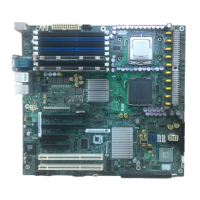
Figure 1. Intel
®
Server Board S1200BTL .................................................................................. 1
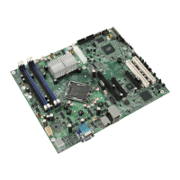
Figure 2. Intel
®
Server Board S1200BTS Picture ..................................................................... 2
Figure 3. Connector and Component Location ......................................................................... 7
Figure 4. Intel
®
Server Board S1200BTS Layout...................................................................... 9
Figure 5. Jumper Blocks (J2G1, J1G1, J1H3, and J2J1) on S1200BTS................................. 10
Figure 6. Configuration Jumpers Location .............................................................................. 12
Figure 7. Back Panel Connectors............................................................................................ 12
Figure 8. Intel
®
SAS Entry RAID Module ................................................................................ 16
Figure 9. Main Screen............................................................................................................. 24
Figure 10. Advanced Screen................................................................................................... 27
Figure 11. Processor Configuration Screen ............................................................................ 29
Figure 12. Memory Configuration Screen ............................................................................... 36
Figure 13. Mass Storage Controller Configuration Screen...................................................... 39
Figure 14. Serial Port Configuration Screen............................................................................ 42
Figure 15. USB Configuration Screen..................................................................................... 42
Figure 16. PCI Configuration Screen ...................................................................................... 43
Figure 17. System Acoustic and Performance Configuration.................................................. 44
Figure 18. Security Screen...................................................................................................... 46
Figure 19. Server Management Screen (S1200BTL).............................................................. 49
Figure 20. Server Management Screen (S1200BTS) ............................................................. 50
Figure 21. Console Redirection Screen .................................................................................. 50
Figure 22. System Information Screen (S1200BTL) ............................................................... 51
Figure 23. System Information Screen (S1200BTS) ............................................................... 52
Figure 24. BMC LAN Configuration Screen (S1200BTL) ........................................................ 53
Figure 25. Hardware Monitor Screen, Auto Fan Control (S1200BTS) .................................... 54
Figure 26. Hardware Monitor Screen, Manual Fan Control (S1200BTS)................................ 54
Figure 27. Realtime Teperature and Voltage Status Screen (S1200BTS).............................. 55
Figure 28. Boot Options Screen.............................................................................................. 56
Figure 29. Hard Disk Order Screen......................................................................................... 57
Figure 30. CDROM Order Screen........................................................................................... 57
Figure 31. Floppy Order Screen.............................................................................................. 58
Figure 32. Network Device Order Screen ............................................................................... 58
Figure 33. BEV Device Order Screen ..................................................................................... 59
Figure 34. Add EFI Boot Option Screen.................................................................................. 59
Figure 35. Delete EFI Boot Option Screen.............................................................................. 60
Figure 36. Boot Manager Screen ............................................................................................ 60
Figure 37. Error Manager Screen............................................................................................ 61
Figure 38. System Event Log Screen (S1200BTS)................................................................. 61
Figure 39. Exit Screen............................................................................................................. 62
Figure 40. BIOS Recovery Jumper ......................................................................................... 65
Figure 41. Password Recovery Jumper .................................................................................. 66
Figure 42. CMOS Recovery Jumper ....................................................................................... 67
 Loading...
