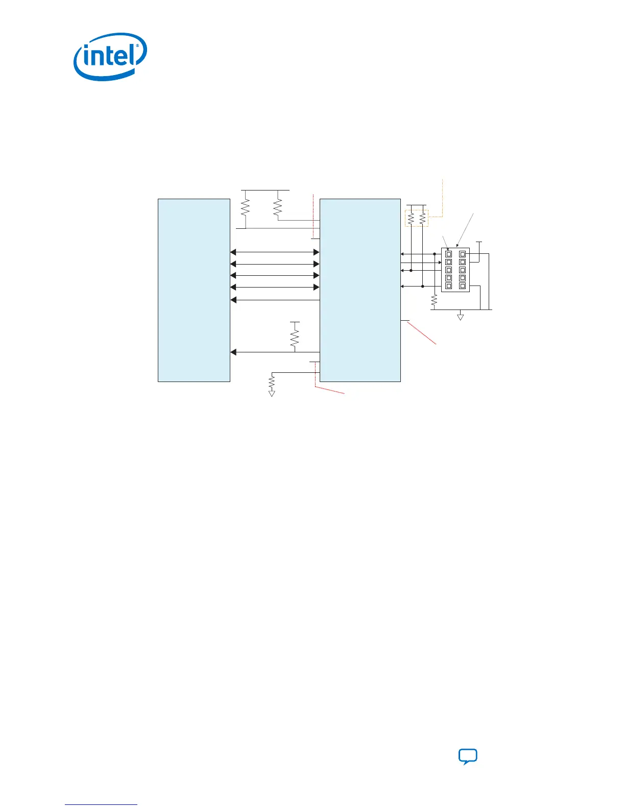
3.2.4.1. Programming Serial Flash Devices using the JTAG Interface
Figure 27. Connection Setup for Programming the Serial Flash Devices using the JTAG
Interface
Download Cable
10-Pin Male Header
(JTAG Mode) (Top View)
TDI
TMS
TDO
TCK
Pin 1
1 kΩ
Resistor values can vary between 1 kΩ to 10 kΩ.
Perform signal integrity analysis to select
the resistor value for your setup.
AS_DATA[0]
AS x4 Flash Device
Intel Stratix 10
nSTATUS
nCONFIG
CONF_DONE
OSC_CLK_1
DATA0
DATA1
DATA2
DATA3
DCLK
nCS
AS_DATA[1]
AS_DATA[2]
AS_DATA[3]
AS_CLK
4.7 kΩ
GND
GND
V
CCIO_SDM
V
CCIO_SDM
10 kΩ
V
CCIO_SDM
10 kΩ
4.7 kΩ
V
CCIO_SDM
MSEL [0]/AS_nCSO[0]
MSEL [1]
MSEL [2]
AS fast mode: Pull MSEL [1] low using 4.7 kΩ resistor
AS normal mode: Pull MSEL [1] high using 4.7 kΩ resistor
External clock source to feed
the Intel Stratix 10 is optional.
For external ref clk, OSC_CLK_1
is required.
CONF_DONE connection
to external host for
monitoring is optional.
3M Part number : 2510-6002UB
Intel recommends using the JTAG interface to prepare the QSPI flash device for later
use in AS mode. Set the MSEL mode to JTAG for when programming the AS x4 device
with a .jic file.
This configuration scheme includes the following steps:
1. In the Intel Quartus Prime Programmer, select the JTAG programming mode and
initiate programming by clicking Start.
2.
The Programmer drives .jic configuration data to the board using the JTAG
header connection.
3. The programmer first configures the SDM with configuration firmware. Then, the
SDM drives configuration data from the programmer to the AS x4 flash device
using SDM_IOs.
4. To use the Intel Stratix 10 device in AS mode after successful programming of the
flash device, set the MSEL pins to either AS fast or AS normal mode
and power cycle the device.
3.2.5. Serial Flash Memory Layout
Serial flash devices store the configuration data in sections.
The following diagram illustrates sections of a non-HPS Intel Stratix 10 configuration
data mapping in serial flash device. Refer to Intel Stratix 10 SoC FPGA Bitstream
Sections of the HPS Technical Reference Manual for more information about flash
memory layout for HPS devices.
3. Intel Stratix 10 Configuration Schemes
UG-S10CONFIG | 2018.11.02
Intel Stratix 10 Configuration User Guide
Send Feedback
56
 Loading...