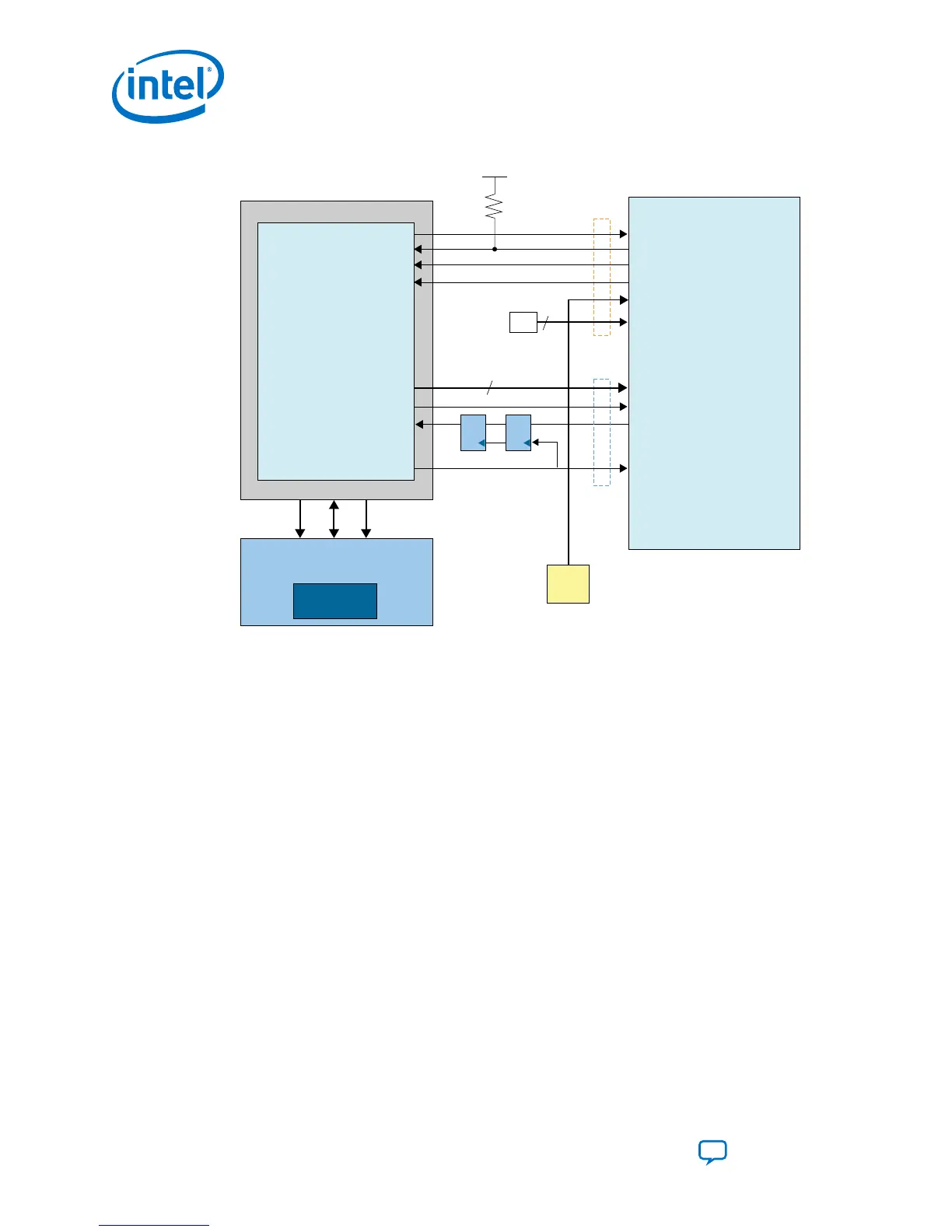
Figure 10. Connections for Avalon-ST x32 Single-Device Configuration
Intel® Stratix®10
nCONFIG
nSTATUS
CONF_DONE
INIT_DONE
OSC_CLK_1
MSEL[2:0]
AVST_DATA [31:0]
AVST_VALID
AVST_READY
AVST_CLK
Configuration
Data Signals
Configuration
Control Signals
Synchronizers
Compact Flash Interface
External Compact Flash Memory
ADDR DATA
.rbf
(little endian)
Control
CPLD / FPGA
External Host
fpga_clk
fpga_ready
fpga_valid
fpga_conf_done
fpga_nstatus
fpga_nconfig
fpga_data [31:0]
10kΩ
MSEL
V
CCIO_SDM
32
3
External Clock Source
(2)
(1)
Parallel Flash Loader II IP
or
Microprocessor
or
Custom Logic
Note: The synchronizers shown in all three figures can be internal if the host is an FPGA or
CPLD. If the host is a microprocessor, you must use discrete synchronizers.
Notes for Figure:
1. Refer to MSEL Settings for the correct resistor pull-up and pull-down values for all
configuration schemes.
2. The synchronizers shown in all three figures can be internal if the host is an FPGA
or CPLD. If the host is a microprocessor, you must use discrete synchronizers.
Related Information
• MSEL Settings on page 18
• Intel Stratix 10 Device Family Pin Connection Guidelines
3.1.4. RBF Configuration File Format
If you do not use the Parallel Flash Loader II Intel FPGA IP core to program the flash,
you must generate the .rbf file.
The data in .rbf file are in little-endian format
3. Intel Stratix 10 Configuration Schemes
UG-S10CONFIG | 2018.11.02
Intel Stratix 10 Configuration User Guide
Send Feedback
32
 Loading...