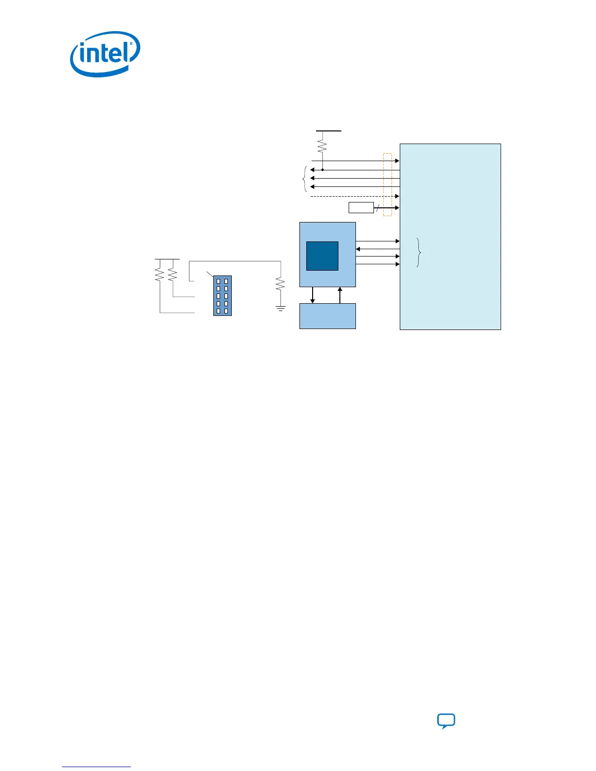
Figure 33. Connection Setup for JTAG Single-Device Configuration using a
Microprocessor
Pin 1
R
UP
R
DN
R
UP
TCK
TDO
TMS
OPEN
TDI
GND
VCCIO_SDM
OPEN
OPEN
GND
G
ND
V
CCIO_SDM
Intel® Stratix®10
nCONFIG
nSTATUS
CONF_DONE
INIT_DONE
OSC_CLK_1
MSEL[2:0]
TCK
ADDR DATA
Memory
Micro Processor
TDO
TDI
TMS
TCK
TDO
TDI
TMS
Configuration
Control Signals
JTAG
Configuration
Pins
Optional
Monitoring
10kΩ
Optional
MSEL
V
CCIO_SDM
3
JAM
Player
Related Information
Intel Stratix 10 Device Family Pin Connection Guidelines
3.4.2. JTAG Multi-Device Configuration
You can configure multiple devices in a JTAG chain. Observe the following pin
connections and guidelines for this configuration setup:
• One JTAG-compatible header connects to several devices in a JTAG chain. The
drive capability of the download cable is the only limit on the number of devices in
the JTAG chain.
•
If you have four or more devices in a JTAG chain, buffer the TCK, TDI, and TMS
pins with an on-board buffer. You can also connect other Intel FPGA devices with
JTAG support to the chain.
3. Intel Stratix 10 Configuration Schemes
UG-S10CONFIG | 2018.11.02
Intel Stratix 10 Configuration User Guide
Send Feedback
66
 Loading...