5.4. Remote System Upgrade Flash Device Layout
The Intel Quartus Prime Programming Files Generator populates the flash memory
when you generate the remote system upgrade programming files.
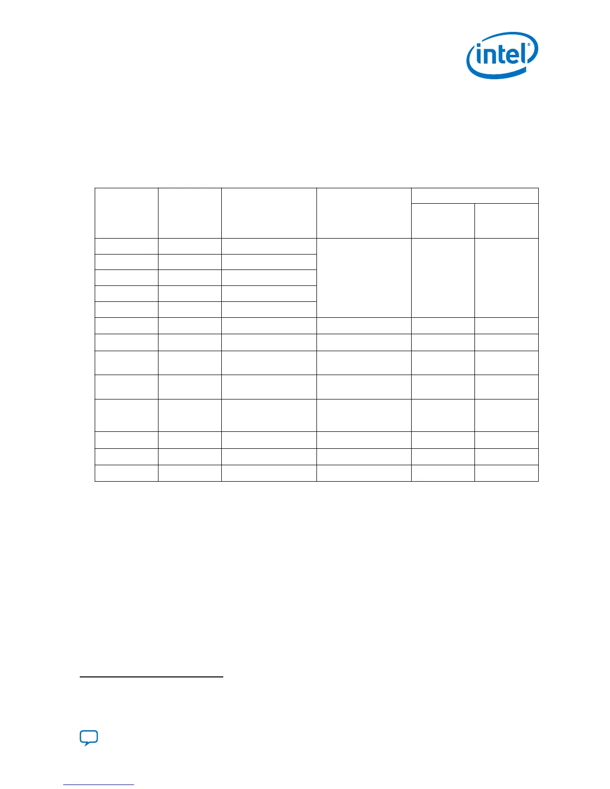
Table 30. Remote System Upgrade Flash Memory Layout
The start of flash address 0, or the A2 partition within a partitioned flash address 0, must be set up as shown
in the following table.
Offset Size (Byte) Usage Sub-Partition Name Sub-Partition Flag
Reserved
Address
(Bit 0)
Read-Only
(Bit 1)
0k 256k Static Firmware Section
BOOT_INFO (remote
system upgrade boot
image)
YES YES
256k 256k Static Firmware Section
512k 256k Static Firmware Section
768k 256k Static Firmware Section
1M 64k Reserved
1M+64k Varies Factory Image
FACTORY_IMAGE
YES YES
Next 32k Sub-partition table
SPT0
YES NO
Next + 32k 32k Sub-partition table
(Back-up copy)
SPT1
YES NO
Next + 32k 32k Configuration firmware
pointer block
CPB0
YES NO
Next + 32k 32k Configuration firmware
pointer block (Back-up
copy)
CPB1
YES NO
Varies Varies Application image 1
APP_IMAGE1
(14)
NO NO
Varies Varies Application image 2
APP_IMAGE2
(14)
NO NO
Varies Varies Application image N
APP_IMAGEN
(14)
NO NO
5.4.1. Configuration Firmware Pointer Block (CPB)
The configuration firmware accesses the configuration firmware pointer block when
performing remote system upgrade. The Intel Quartus Prime Programming Files
Generator sets up the initial configuration firmware pointer block. Each copy of the
configuration firmware pointer block (CPB0/CPB1) must be exactly 4 KB.
(14)
User-assigned sub-partition name.
5. Remote System Upgrade
UG-S10CONFIG | 2018.11.02
Send Feedback
Intel Stratix 10 Configuration User Guide
83
 Loading...