FB250/Fleet One - Marine Satellite Communication System
24
5.3 Mast Designing (Installation Example)
The installation mast must be robust enough to prevent flex, vibration, and sway when an external force is
exerted on the mast with antenna and radome. Refer to the following mast drawings for more details.
WARNING
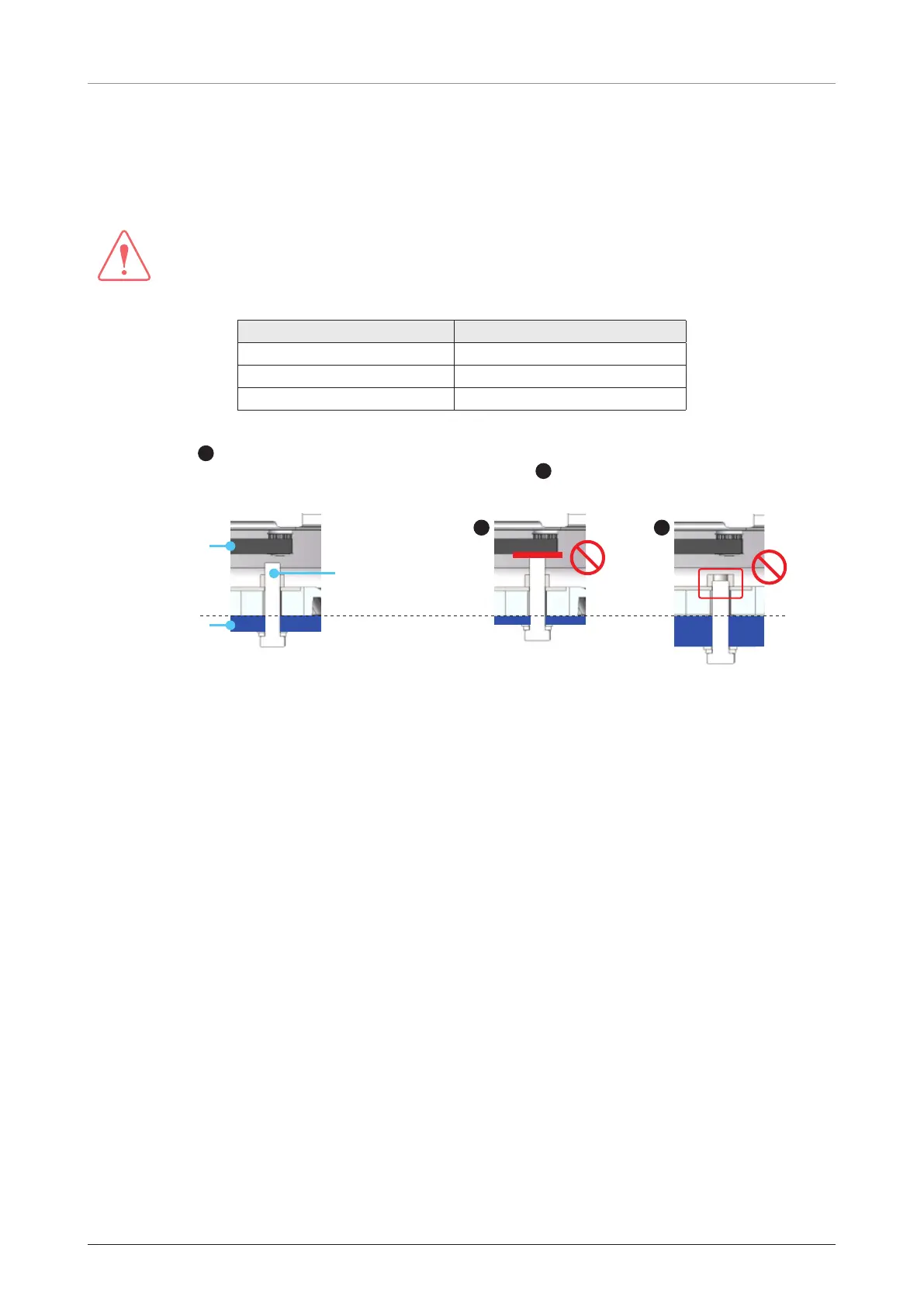
When designing a mast, consider the minimum and maximum thickness of the mast plate marked on the
diagram. If the thickness of the mast plate is different from the recommended size (Min. 6.0 mm / Max. 8.0
mm), choose right sized bolts for mounting antenna on the mast according to the table below.
Mast Plate Thickness Recommended Bolt Size
3 ~ 5 mm M6 x 25 L
6 ~ 8 mm (Recommended) M6 x 30 L (Supplied)
9 ~ 12 mm M6 x 35 L
• To use the supplied bolts (M6 x 30 L) for mounting antenna on a mast, the thickness of mast plate must
be 6 ~ 8 mm.
A
If the mast plate is thinner than 6 mm, the bolt thread stick-out protruding beyond the
nut inside the radome can damage the AZ belt of the antenna.
B
If the mast plate is thicker than 8 mm,
the supplied antenna-mast mounting bolts can be too short to mount the antenna on the mast securely.
When the mast plate
thickness is 6 ~ 8 mm
AZ Belt
*Mast Plate
Supplied Bolt:
M6 x 30 L
When the mast plate is
thinner than 6 mm
A
When the mast plate is
thicker than 8 mm
B
 Loading...