FB250/Fleet One - Marine Satellite Communication System
44
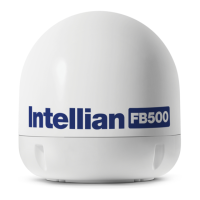
6.6.8 Connecting BDU to External Devices
The BDU has a dedicated 16-pin connector to provide a GPIO (General Purpose Input/Output) interface to
the external devices. All wires for the GPIO port must use AWG 24 unscreened wire type. Connect the end
of these AWG 24 wires to the GPIO port’s Pin A (point 1) and Pin B (point 2) respectively.
GPIO
BDU
External
Devices
Figure 36: BDU to External Devices Connection
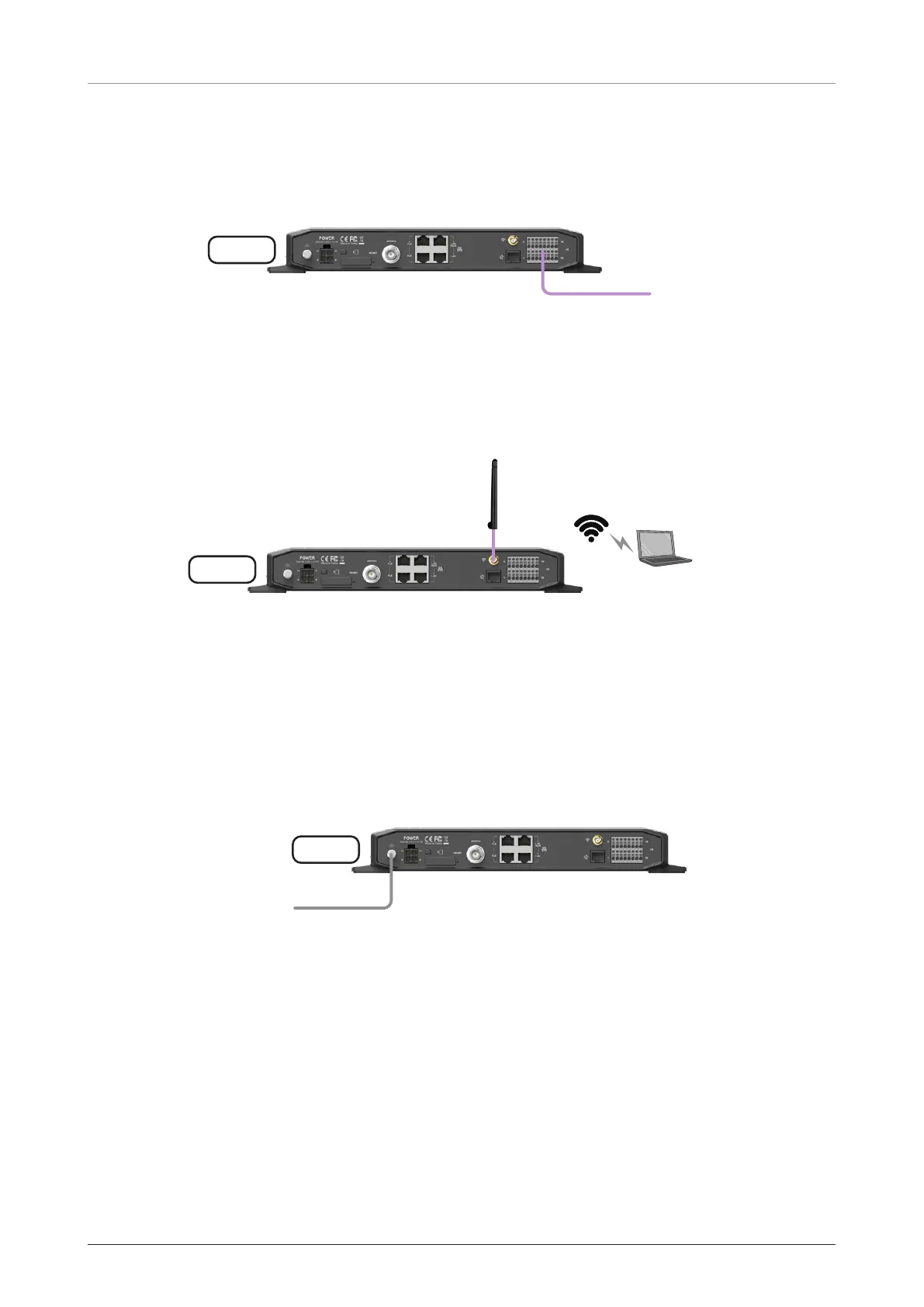
6.6.9 Connecting Wi-Fi Antenna to BDU
Intellian provides the Wi-Fi Antenna for Wi-Fi connection. Plug the Wi-Fi Antenna into the Wi-Fi port on the
back of the BDU.
Wi-Fi Antenna
BDU
Wi-Fi
Wireless
Devices
Figure 37: Wi-Fi Antenna to BDU Connection
6.6.10 Grounding Stud
The BDU should be grounded. Use a heavy ground cable (customer supplied) to connect the BDU to the
vessel’s ground during normal use. A safety grounding system is necessary to protect your radio hardware
from lightning strikes and the build-up of static electricity. The grounding system must comply with the
safety standards that apply in your country.
Ground the BDU using a heavy ground cable (not included) from the Grounding Stud of the BDU back
panel to the vessel’s ground to protect the system from unwanted surges and voltage differentials.
Vessel’s
Ground
BDU
Grounding Stud
Figure 38: Grounding Stud Connection
 Loading...