FB250/Fleet One - Marine Satellite Communication System
46
Chapter 7. Operating BDU
The BDU and ADU are connected by a single coaxial cable through which power and Ethernet data are
delivered between the BDU and ADU. The BDU is responsible for all the terminal management, system
monitoring, control, error detection, and maintenance operations.
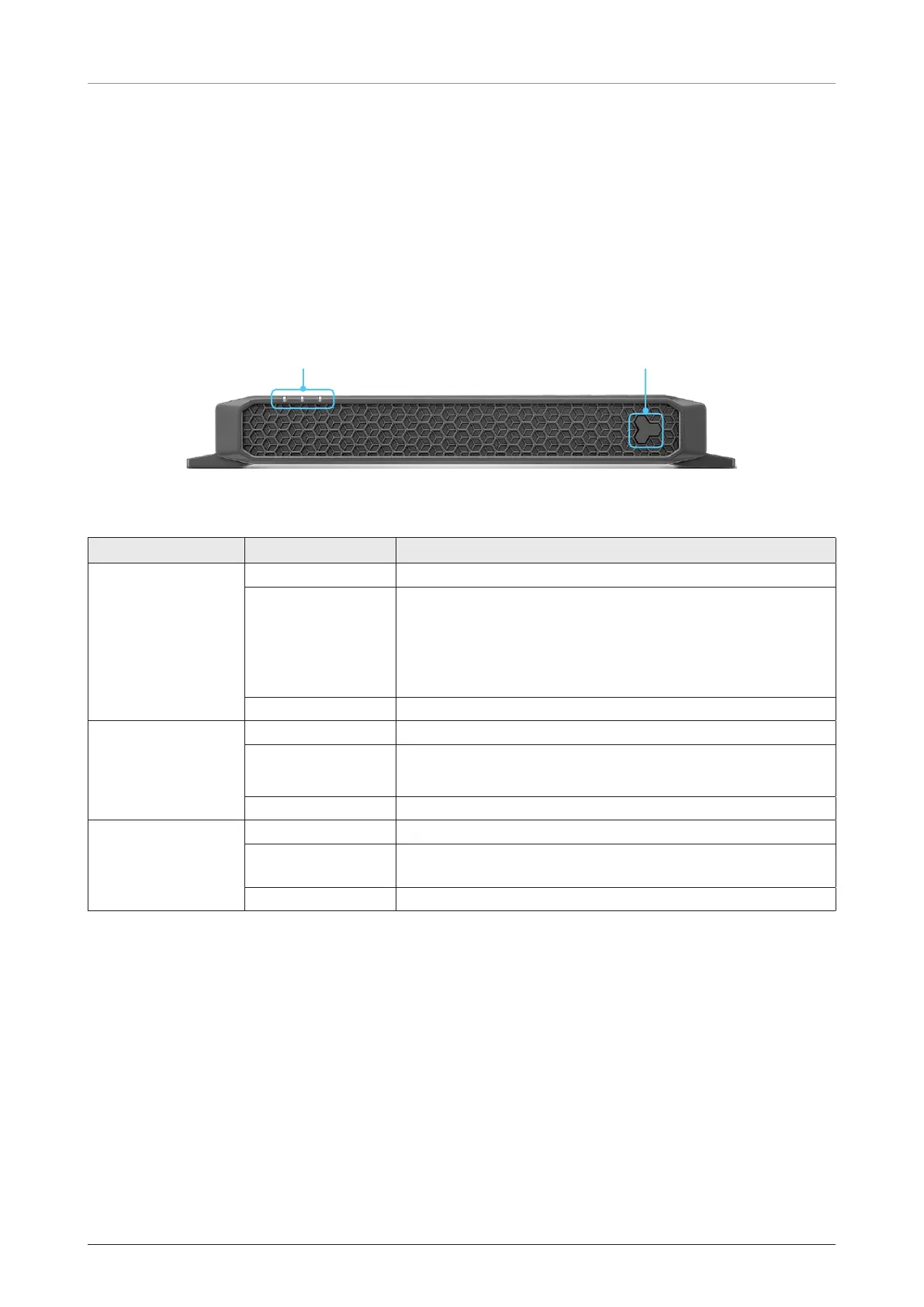
7.1 BDU Front Panel
The following figure shows the BDU’s front panel.
LED Indicator Power Button
Figure 39: BDU Front Panel
The following table shows status indicators on the face of BDU.
LED Indicator Color Description
Power
Off The terminal is powered off.
Blinking
The terminal is booting a system.
The terminal is calibrating a system.
The terminal is in error.
There is no USIM card inside BDU.
Steady Green The terminal is powered on.
Satellite
Off The system is not connected to a satellite.
Blinking
The system is acquiring a satellite.
The system is searching for a satellite.
Steady Green The system is connected to a satellite.
Event
Off The system has no event (call or data).
Blinking
The system has an alert, an unread message, an incoming
call.
Steady Green The system has a voice or data.
NOTE: When 3 LEDs blink simultaneously, the BDU is in a low power state. Check the current input voltage
status.

 Loading...