Installing BDU
37
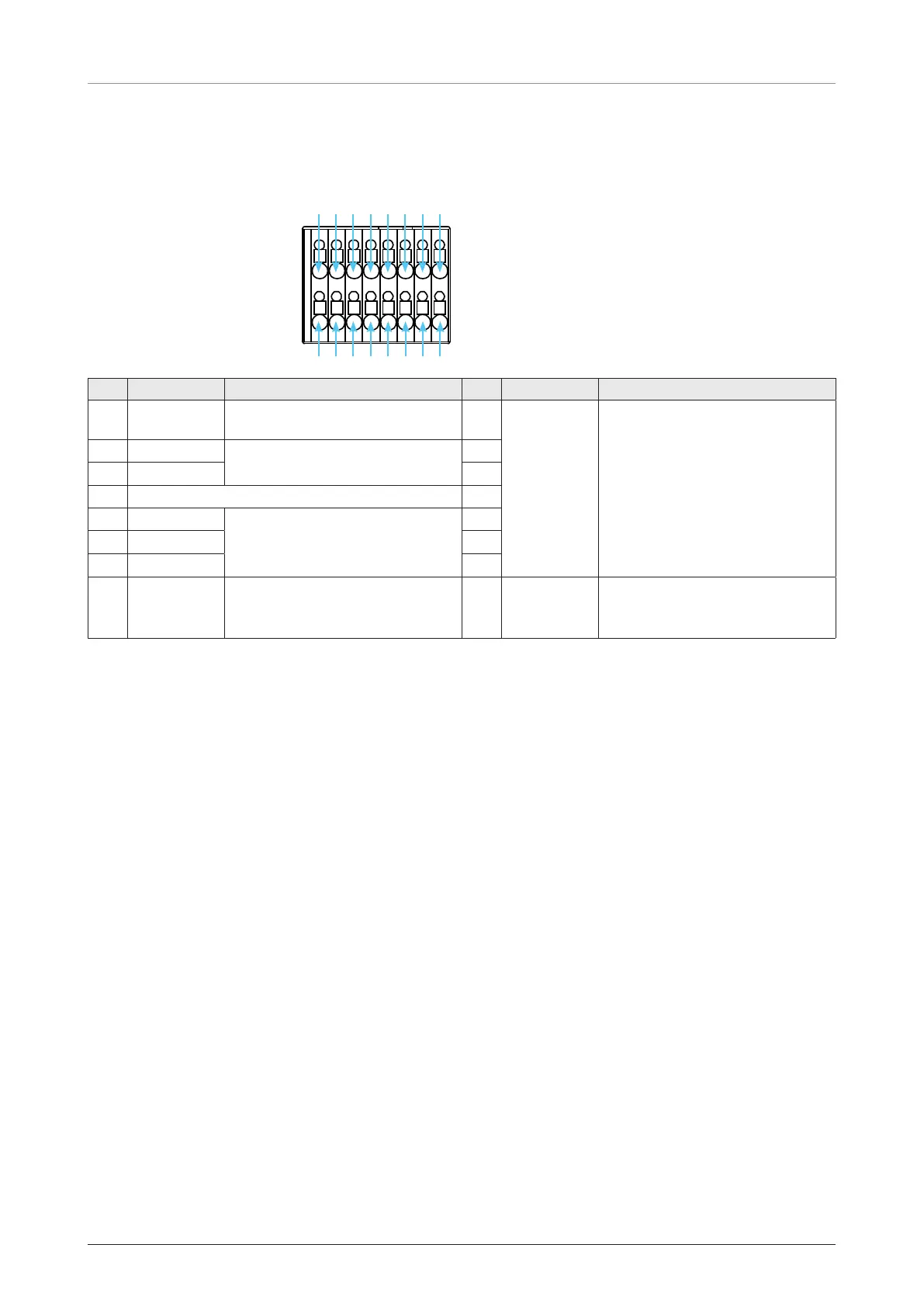
General Purpose Inputs/Outputs (GPIO) Connector
The BDU has a dedicated 16-pin connector to provide a GPIO (General Purpose Input/Output) interface to
the external devices. All wires for the GPIO connector must use AWG 24 unscreened wire type.
16-Pin Terminal Block
1
2
9
10
5
6
13
14
3
4
11
12
7
8
15
16
Pin Signal Explanation Pin Signal Explanation
1
External
Power Input
Power Input
(DC 12 V ~ DC 24 V)
2
External
Power
Ground
Input/Output Ground
3 Input 1
• Satellite Data Prevention
• Force Prevent RF Activity
4
5 Input 2 6
7 N/A 8
9 Output 1
• Incoming Call Alarm
• Data Connection Indication
• System Event Indication
10
11
Output 2
12
13 Output 3 14
15
Remote
Power On/
Off +
Remote Control of BDU Power + 16
Remote
Power On/
Off -
Remote Control of BDU Power -
Figure 29: GPIO Connector Pinout

 Loading...