Installing BDU
35
6.6 BDU Cable Connection
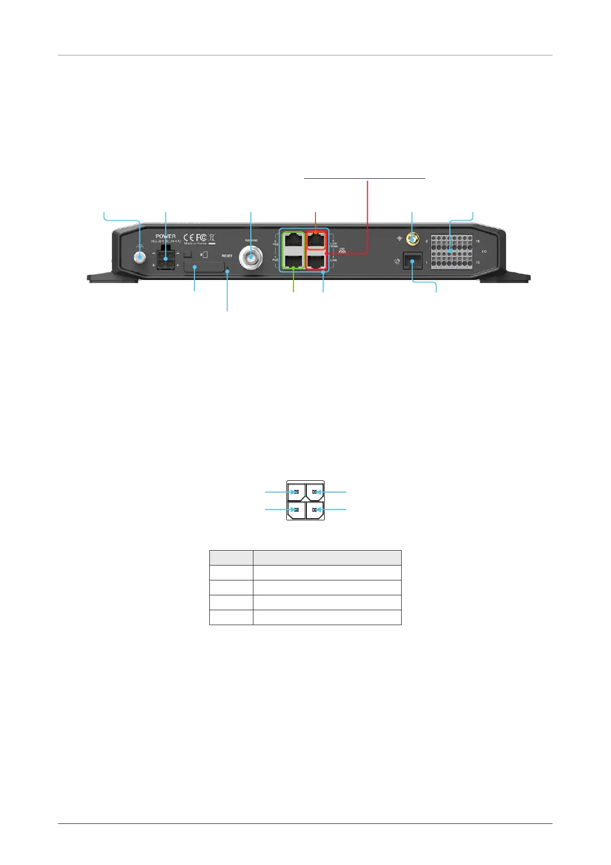
6.6.1 BDU Back Panel View
The following figure shows the BDU back panel.
* LAN (Local Area
Network ) 1, 2, 3,
4 (RJ45)
USIM
Card
Reset
POTS (Plain Old Telephone
Service) Phone (RJ14)
Antenna (TNC)
WAN (Wide Area
Network)
* NOT supported for Fleet One.
Power Grounding Wi-Fi GPIO
**PoE (Power
over Ethernet)
1, 2 (RJ45)
* All LAN ports are IEEE 802.3 compliant.
** Each PoE Port is designed to use 7.5 W power. When using over
12.5 W in one port, the PoE function will be stopped in port 1 or port 2.
Figure 24: BDU Back Panel View
6.6.2 BDU Connector Pinout Guide
The BDU connector pins and their corresponding descriptions are shown in the following figures and tables.
Power Connector (DC Power)
Pin 4 ( - )Pin 3 ( - )
Pin 2 ( + )Pin 1 ( + )
4 Contact Power Plug Male
Pin Signal
1 +
2 +
3 -
4 -
Figure 25: DC Power Connector Pinout
 Loading...