Goodrive300-01A-RT series integrated machine Function description
-43-
Description Default Modify
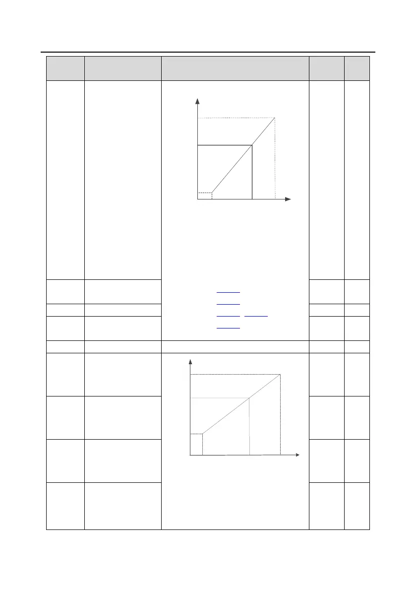
The corresponding percentage is obtained
based on the relationship between t
and lower limits and their corresponding
settings, shown in the following figure.
Present pressure = corresponding
percentage × pressure sensor P1 upper limit
Setting range of P05.32: 0.00V–P05.34
Setting range of P05.33: -100.0%–100.0%
Setting range of P05.34: P05.32–10.00V
Setting range of P05.35: -100.0%–100.0%
2.00V ○
Corresponding setting
of P1 lower limit
0.0% ○
10.00V ○
Corresponding setting
of P1 upper limit
100.0% ○
0.000s–10.000s 0.200s ○
Corresponding setting of the upper and
lower limits are set as a percentage that
temperature calibration point
total range, and analog percentage
corresponding to input voltage can be
0.00V ○
Corresponding setting
of PT1 lower limit
12.5% ○
10.00V ○
Corresponding setting
of PT1 upper limit
P05.32
P05.34
Input voltage
17.19
P05.33
P05.35
Corresponding
percentage
Corresponding setting (%)
0
P18.29
P18.28
P05.38
P05.39
17.20
Correspond
ing
percentage
Corresponding setting (%)
Input voltage
 Loading...


