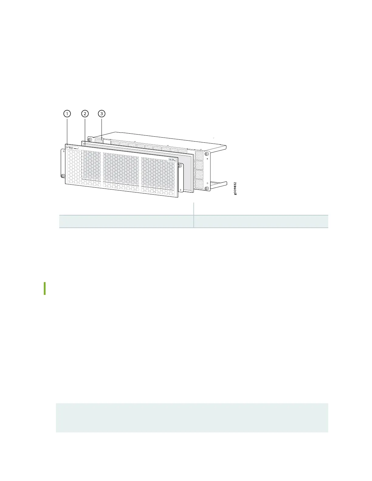
The air filter is located at the center of the air filter unit, and just behind the outer filter cover. See
Figure 37 on page 122.
4. Grasp the air filter, and place the air filter straight onto inner filter cage.
Figure 37: Installing the Air Filter into the Air Filter Unit
3—1— Inner filter cageOuter filter cover
2—Air filter
5. Place the outer air filter cover back into it’s place, and tighten the captive screws to secure the air filter
unit.
Maintaining the MX10003 Fan Module
Purpose
For optimum cooling, verify the condition of the fans.
Action
•
Monitor the status of the fans. A fan module contains multiple fans that work in unison to cool the router
components. If one fan fails, the router adjusts the speed of the remaining fans to maintain proper
cooling. A red alarm is triggered when a fan fails, and when a fan module is removed.
•
To display the status of the cooling system, issue the show chassis environment command. The output
is similar to the following:
user@host> show chassis environment
Class Item Status Measurement
Temp CB 0 Top Right Inlet Sensor OK 35 degrees C / 95 degrees F
122