routers, you must connect a grounding cable to earth ground and then attach it to the chassis grounding
points by using the two screws provided.
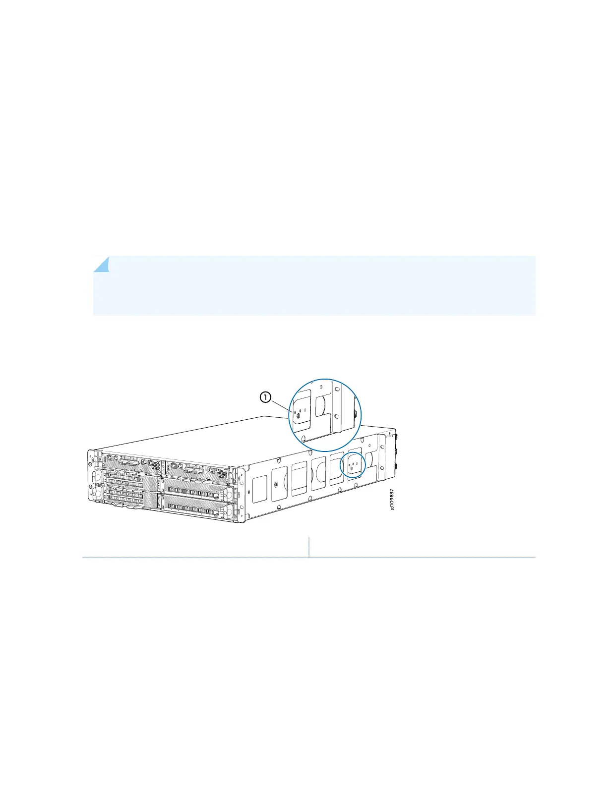
Figure 18 on page 62 shows the grounding point location on the router.
A protective earthing terminal bracket is required for connecting the chassis to earth ground. This two-holed
bracket attaches on the side of the chassis through the mounting rail and provides a protective earthing
terminal for the switch. The grounding points are studs sized for M4 hex screws. M4 hex screws with
integrated washers are provided in the accessory kit. The grounding points are spaced at 0.75-in. (19.1-mm)
centers.
Two threaded holes are provided on the front right side of the chassis for connecting the router to earth
ground. The grounding points fit M5 pan head screws.
NOTE: Additional grounding is provided to an AC-powered router when you plug its power
supplies into grounded AC power receptacles.
Figure 18: Grounding Points on the Router
1—Grounding point
Grounding Cable Lug Specifications
The accessory box shipped with the router includes one cable lug that attaches to the grounding cable
and M4 hex screws used to secure the grounding cable to the grounding points .
62