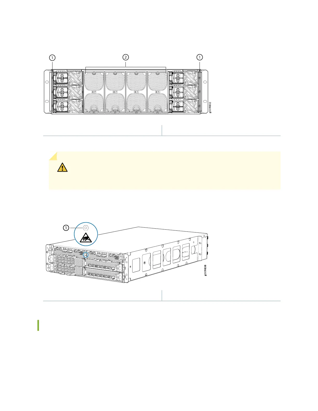
Figure 3: Rear View of the DC-Powered MX10003 Router
2—1— Fan modulesPower supply modules (DC)
Figure 4 on page 27 shows the electrostatic discharge (ESD) point on the router.
CAUTION: Before removing or installing components, attach an ESD strap to an ESD
point, and place the other end of the strap around your bare wrist. Failure to use an
ESD strap could result in damage to the hardware components.
Figure 4: ESD Point on the MX10003 Router
1—ESD point
MX10003 Front and Rear Panel Components
The front panel on the front of the router enables you to view status and troubleshooting information at
a glance. The front panel contains LEDs for the router components, online/offline and reset buttons,
auxiliary and console ports, clocking ports, and ports for the 10-Gigabit Ethernet MIC.
27