Trigger model (GPIB operation)
This section describes how the Model 2000 Multimeter operates over the GPIB bus. The
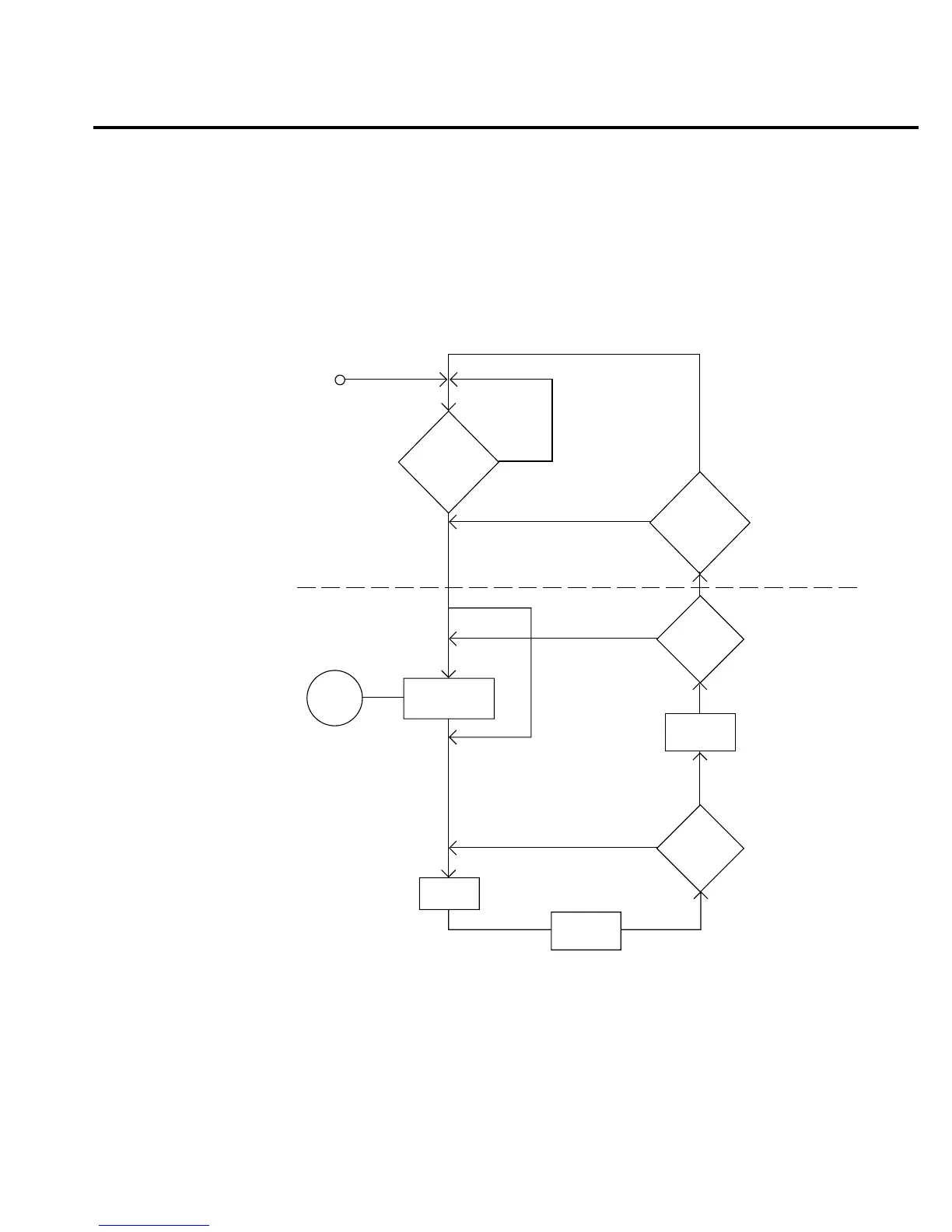
flowchart in Figure 4-11 summarizes operation over the bus and is called the trigger model. It is
called the trigger model because operation is controlled by SCPI commands from the Trigger
subsystem (see Section 5 for more information). Key SCPI commands are included in the trigger
model.
:ABOrt
*RCL
:SYST:PRES
Language Change
No
Yes
Idle
and
Initiate
:Trigger:Signal
Control
Source
:Trigger:Source Immediate
:Trigger:Source External
:Trigger:Source Timer
:Trigger:Source Manual
:Trigger:Source BUS
:Trigger:Delay <n>
:Trigger:Delay:AUTO <b>
Delay
Device
Action
(see Figure 4-12)
:Sample:Count <n>
Another
Sample
?
:Trigger:Count <n> Infinite
Another
Trigger
?
:INIT (:IMM)
or
:INIT:CONT ON
?
Event
Detection
:INIT (:IMM)
or
:INIT:CONT ON
?
No
No
No
Yes
Yes
Output
Trigger
Yes
Remote Operation 4-29
Figure 4-11
Trigger model
(remote opera-
tion)