Low level considerations
For sensitive measurements, external considerations beyond the Model 2000 affect the accu-
racy. Effects not noticeable when working with higher voltages are significant in microvolt sig-
nals. The Model 2000 reads only the signal received at its input; therefore, it is important that
this signal be properly transmitted from the source. The following paragraphs indicate factors
that affect accuracy, including stray signal pick-up and thermal offsets.
Shielding
AC voltages that are extremely large compared with the DC signal to be measured may pro-
duce an erroneous output. Therefore, to minimize AC interference, the circuit should be shield-
ed with the shield connected to the Model 2000 INPUT LO (particularly for low level sources).
Improper shielding can cause the Model 2000 to behave in one or more of the following ways:
• Unexpected offset voltages.
• Inconsistent readings between ranges.
• Sudden shifts in reading.
To minimize pick-up, keep the voltage source and the Model 2000 away from strong AC mag-
netic sources. The voltage induced due to magnetic flux is proportional to the area of the loop
formed by the input leads. Therefore, minimize the loop area of the input leads and connect each
signal at only one point.
NOTE Shielded cables should be used for input circuits to avoid interference caused by
conducting RF.
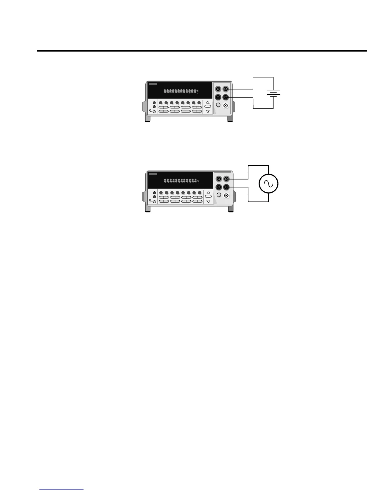
2001 MULTIMETER
Caution: Maximum Input = 750V RMS, 1000V peak, 8 x 10
7
V•Hz
AC Voltage
Source
Model 2000
Input Impedence = 1MΩ and 100pF
SHIFT
CH1REM
TALK
LSTN
SRQ
STATREL FILT
4W
BUFFER
MATH
REAR
SCAN
TIMER
STEP CH2 CH3 CH4 CH5 CH6 CH7 CH
8
CH9 CH1
0
HOLD TRIG FAST MED SLOW AUTO ERR
2001 MULTIMETER
Model 2000
Caution : Maximum Input = 1010V peak
DC Voltage
Source
Input Resistance = 10MΩ on 1000V and 100V ranges ;
> 10GΩ on 10V, 1V and 100mV ranges.
SHIFT
CH1REM
TALK
LSTN
SRQ
STATREL FILT
4W
BUFFER
MATH
REAR
SCAN
TIMER
STEP CH2 CH3 CH4 CH5 CH6 CH7 CH8 CH9 CH10
HOLD TRIG FAST MED SLOW AUTO ERR
Basic Measurements 2-19
Figure 2-4
DC and AC voltage
measurements