GPIB bus connections
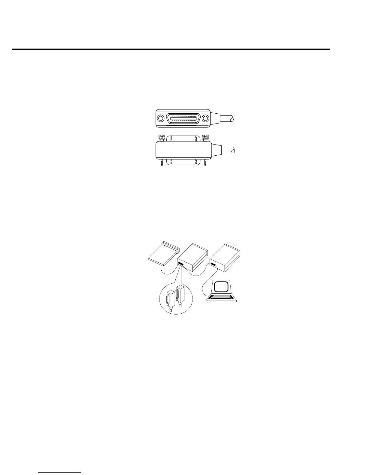
To connect the Model 2000 multimeter to the GPIB bus, use a cable equipped with standard
IEEE-488 connectors as shown in Figure 4-2.
To allow many parallel connections to one instrument, stack the connector. Two screws are
located on each connector to ensure that connections remain secure. Current standards call for
metric threads, which are identified with dark-colored screws. Earlier versions had different
screws, which were silver-colored. Do not use these types of connectors on the Model 2000 mul-
timeter, because it is designed for metric threads.
Figure 4-3 shows a typical connecting scheme for a multi-unit test system.
To avoid possible mechanical damage, stack no more than three connectors on any one unit.
NOTE
To minimize interference caused by electromagnetic radiation, use only shielded
IEEE-488 cables. Available shielded cables from Keithley are models 7007-1 and
7007-2.
Instrument
Controller
InstrumentInstrument
4-10 Remote Operation
Figure 4-2
IEEE-488 con-
nector
Figure 4-3
IEEE-488 con-
nections