Front Panel Operation
2-99
DISABLED: Use this selection to disable strobe control.
ENABLED: Use this selection to enable strobe control.
PASS-PATTERN
This item allows you to program the on/off states of the dig-
ital output lines for when all limit tests pass. Note that when
the binning strobe is enabled, digital output line #4 cannot be
used.
Selecting PAS-PATTERN displays the digital output pattern
that occurs when all limit tests pass. To change the pattern,
use the cursor keys and the range keys. The range keys toggle
the parameter values between OFF and ON.
Limits example
This example sorts a quantity of 100Ω resistors into five bins,
according to the following tolerances:
• Values less than 90Ω (outside -10% tolerance).
• Values greater than 110Ω (outside +10% tolerance).
• Values between 90Ω and 99Ω (meets -10% tolerance).
• Values between 101Ω and 110Ω (meets +10% toler-
ance).
• Values between 99Ω and 101Ω (meets ±1% tolerance).
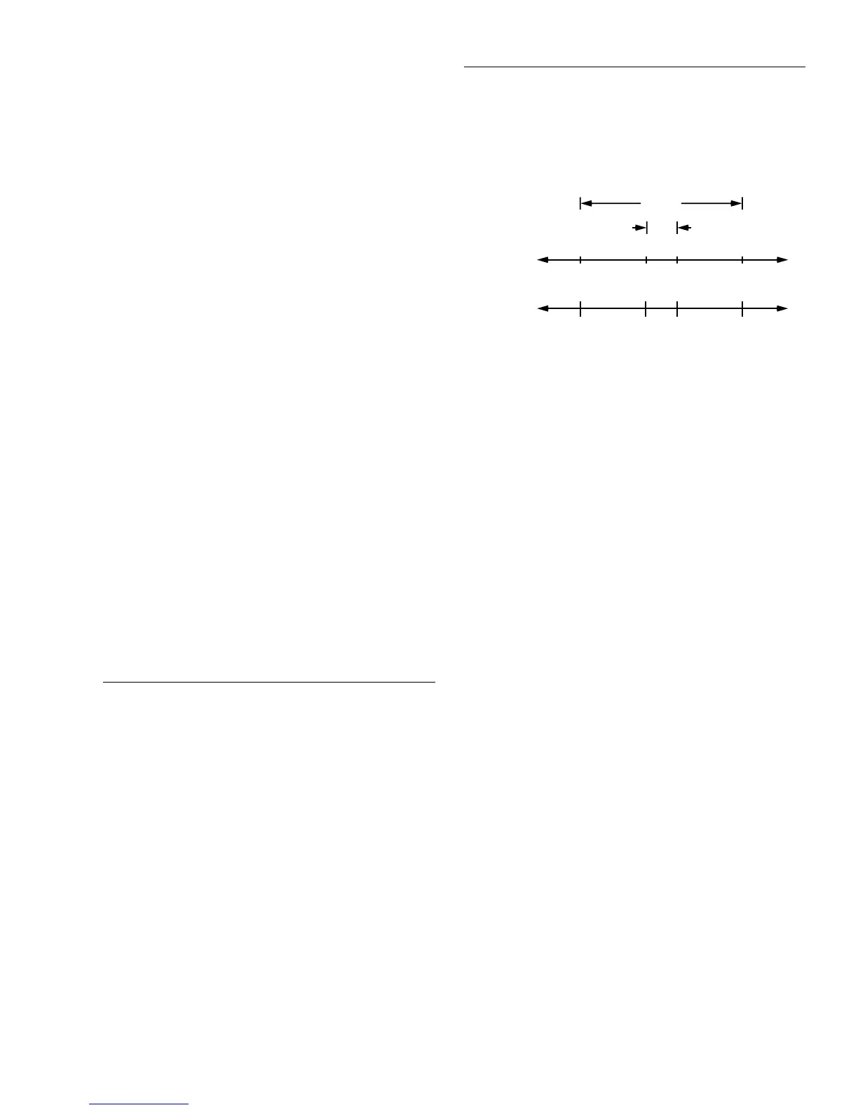
The desired test is shown in Figure 2-35. Use the following
procedure to program the limits:
1. From the LIMITS menu, set the limit values and actions
according to the following table:
2. Enable the binning strobe signal from the STROBE-
CONTROL item of the LIMITS menu.
3. Set a pass pattern of all lines off from the PASS PAT-
TERN item of the LIMITS menu.
4. Enable the control of the digital output lines by limit set
#1 and limit set #2 from the LIMIT SET #1 and LIMIT
SET #2 menus. This sets the digital output lines to the
“pass pattern” (all OFF in this example). Since binning
is enabled, digital output #4 is also OFF.
Note that the actual state (high or low) of the digital output
lines depends on the polarity (ACTIVE-HIGH or ACTIVE-
LOW). This is programmed from the DIGITAL I/O selection
of the GENERAL menu.
2.12.6 STATUS-MSG
This selection is used to enable or disable the status messag-
es mode. When enabled, status messages are displayed to
identify specific operations that are performed.
ON: Enable the status message mode.
OFF: Disable the status message mode.
The instrument may become so busy displaying status mes-
sages, that keypresses are no longer acknowledged. You may
have to clear status message display by pressing the EXIT
key or sending a bus command (:DISPlay:SMESsage OFF)
to get out of this mode.
2.12.7 GENERAL
The GENERAL menu is used for the following operations:
• To control the state and sense of the digital outputs; to
view the state of the digital input.
• To view the serial number, memory option, SCPI ver-
sion, and firmware revision levels of the Model 2002.
• To control the frequency of autozero readings and to set
line synchronization of readings.
• To configure timestamp.
• To choose the character displayed for a decimal.
• To set the real-time clock.
Limit Value Action
LOLIM1 90Ω DIGOUT1=ON, others OFF
HILIM1 110Ω DIGOUT2=ON, others OFF
LOLIM2 99Ω DIGOUT1=ON, DIGOUT2=
ON, others OFF
HILIM2 101Ω DIGOUT3=ON, others OFF
Figure 2-35
Using limit test to sort 100
Ω
resistors
Tolerance
Bands
±10%
±1%
Resistance
Bit
Patterns
and
Limits
90Ω 99Ω 101Ω 110Ω
001 011 000 100 010
LOLIM1 LOLIM2 HILIM2 HILIM1