Front Panel Operation
2-41
2.6.1 Configuring rel
Pressing CONFIGURE REL displays the rel value for the
present measurement function. You can change the rel value
using the cursor keys ( and ) and the RANGE ▲ and
▼ keys. When ENTER is pressed, the instrument returns to
the measurement display state with that value of rel enabled.
If you try to enter an invalid rel value, a message indicating
the rel limit will be displayed and the rel operation will be
cancelled.
Previously stored rel values are converted if temperature or
AC voltage units are changed. For example, a rel value of
100 that was stored with units of DEG-C is converted to 212
if temperature units are changed to DEG-F.
Note that a bench or GPIB reset clears any stored rel values
and disables rel for all functions.
2.6.2 Enabling rel
From the normal reading display, the REL key toggles the rel
operation on and off. Each time rel is enabled by the REL
key, the present reading becomes the new rel value for that
function. You cannot rel an overflow reading.
To make a new reading the rel value, rel must first be dis-
abled and then enabled again. Disabling rel does not clear
any stored rel value.
When rel is enabled, the resulting reading is the algebraic
difference between the actual input value and the rel value:
With math enabled, the rel’d reading is acted on by the math
operation:
A rel value expressed in dB or dBm is applied after the read-
ing is referenced to the selected level.
2.6.3 Multiple display of rel
One of the “multiple displays” allows you to view the read-
ing without rel applied on the bottom line of the display and
the rel’d reading on the top line. The display is available by
repeatedly pressing either the NEXT or PREVious DIS-
PLAY key to scroll through the multiple displays of the par-
ticular function. The following is a typical message for a rel
multiple display:
+000.012 mVAC RMS
Actual=+001.012 (without REL)
2.7 Triggers
The following paragraphs discuss front panel triggering,
trigger configuration, and external triggering, including ex-
ample setups.
Model 2002 triggers are set up in the CONFIGURE TRIG-
GER menu. The menu structure is shown and summarized in
Table 2-27. Some general rules to navigate menus are given
in paragraph 2.3.4.
2.7.1 Trigger model
The following information describes triggering of the Model
2002 from the front panel. The flowchart of Figure 2-12 sum-
marizes front panel triggering. It is called the Trigger Model
because it is patterned after the SCPI commands sent over
the IEEE-488 bus to control triggering.
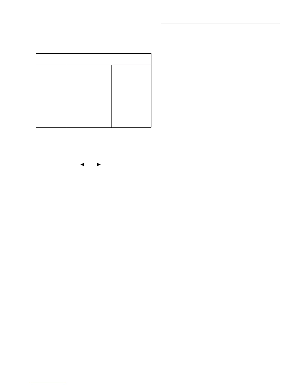
Table 2-26
Allowable rel values
Function Rel range
DC voltage
AC voltage
DC current
AC current
2-wire
resistance
4-wire
resistance
Frequency
Temperature
-1.1e3 to +1.1e3
-7.75e2 to +7.75e2
-1.2e1 to +1.2e1
-2.1e0 to +2.1e0
0 to +1.05e9
0 to +2.1e6
0 to +1.5e7
-3.28e2 to +3.31e3
(±1100V)
(±775V)
(±12A)
(±2.1A)
(0 to 1.05GΩ)
(0 to 2.1MΩ)
(0 to 15MHz)
(-328 to +3310°)
rel'd
reading
=
actual
value
-
relative
value
displayed
reading
=
math
operation
(rel'd
reading)