Front Panel Operation
2-102
Outputs used as logic inputs
To use the digital outputs as logic inputs to active TTL, Low-
power TTL, or CMOS inputs:
1. Connect the Model 2002 digital outputs to the logic
inputs.
2. Connect the digital grounds.
3. Using the STATE menu, check the output state setting of
the Model 2002 output lines. The STATE value for each
output used should be ON.
4. Using the LOGIC-SENSE menu, check the logic-sense
setting of the Model 2002 output lines (TTL1 through
TTL4). Make sure the correct LOGIC-SENSE value is
selected for each output line. The LOGIC-SENSE value
varies according to the type of TTL, Low-power TTL, or
CMOS inputs used (ACTIVE-HIGH or ACTIVE-
LOW).
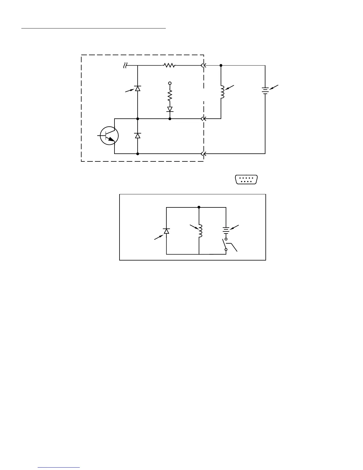
To other three
digital outputs
+5V
10Ω
Digital Output #1
Flyback Diode
Digital I/O Receptacle
51
96
(Connector J1031)
Pin 4 - External Voltage Flyback
connection (+5V to +30V)
Pin 6 - Digital Output #1
Pin 5 - Digital Ground
Relay Coil
(+)
(-)
External Power
(+5V to +30V)
10kΩ
Pull Up Resistor
Relay Coil
(+)
(-)
External Power
(+5V to +30V)
Flyback Diode
Equivalent Circuit
Model 2002
Transistor Switch
Figure 2-38
Sample externally powered relay sample
NOTE
If any LIMITS control is enabled
(LOLIM1 or 2, HILIM1 or 2—High, Low,
or Pass), the OUTPUT-STATE menu does
not check or change the output status. Re-
fer to paragraph 2.12.5 for information on
limits.
Input
The single digital input is located on the digital I/O port (con-
nector J1031, pin 1). The input sense is fixed at active-high
(ON=5V). Use the INPUT menu to change the status of the
input to ON or OFF.