Front Panel Operation
2-54
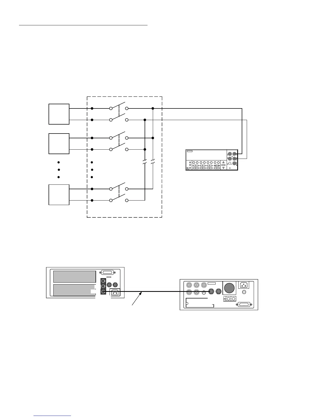
Asynchronous Trigger Link example #1
In a typical test system, you may want to close a channel and
then measure the DUT connected to the channel with a mul-
timeter. Such a test system is shown in Figure 2-19, which
uses a Model 2002 Multimeter to measure ten DUTs
switched by a Model 7011 multiplexer card in a Model 7001/
7002 Switch System.
The Trigger Link connections for this test system are shown
in Figure 2-20. Trigger Link of the Model 2002 is connected
to Trigger Link of the Model 7001/7002 Switch System.
Notice that only one Trigger Link cable is needed.
Figure 2-19
DUT test system
2002 Multimeter
1
DUT
#1
2
DUT
#2
10
DUT
#10
OUTPUT
Card 1
7011 MUX Card
Input HI
Input LO
NEXT
DISPLAY
PREV
POWER
2002 MULTIMETER
SENSE
Ω 4 WIRE
HI
INPUT
LO
INPUTS
CAL
500V
PEAK
F
R
FRONT/REAR
2A 250V
AMPS
350V
PEAK
1100V
PEAK
Figure 2-20
Trigger Link connections (asynchronous example #1)
Trigger
Link
7001 or 7002 Switch System
Trigger
Link Cable
(8501)
2002 Multimeter
IN
OUT
Trigger
Link
IN OUT