Keithley Instruments, Inc.
28775 Aurora Road
Cleveland, Ohio 44139
1-888-KEITHLEY
www.keithley.com
Specifications are subject to change without notice.
SPEC-2002 Rev. H / February 2009 Page 1 of 14
Model 2002
Multimeter Specifications
The following pages contain the complete specifications for the 2002. Every effort has been made to make these specifications complete by
characterizing its performance under the variety of conditions often encountered in production, engineering, and research.
The 2002 provides Transfer, 24-hour, 90-day, 1-year, and 2-year specifications, with full specifications for the 90-day, 1-year, and 2-year
intervals. This allows the operator to utilize 90-day, 1-year, or 2-year recommended calibration intervals, depending upon the level of accuracy
desired. As a general rule, the 2002’s 2-year performance exceeds a 6H-digit DMM’s 90-day, 180-day, or 1-year specifications.
ABSOLUTE ACCURACY
All DC specifications are given as relative accuracies. To obtain absolute accuracies, the absolute uncertainties of the calibration sources must
be added to the relative accuracies. The absolute uncertainties for the calibration sources used during Keithley's factory calibration are given in
a table included in the specifications. The uncertainties of the operator’s sources may be different.
All AC specifications are given as absolute accuracies.
TYPICAL ACCURACIES
Accuracy can be specified as typical or warranted. All specifications shown are warranted unless specifically noted. Almost 99% of the 2002’s
specifications are warranted specifications. In some cases it is not possible to obtain sources to maintain traceability on the performance of
every unit in production on some measurements (e.g., high-voltage, high-frequency signal sources with sufficient accuracy do not exist). These
values are listed as typical.
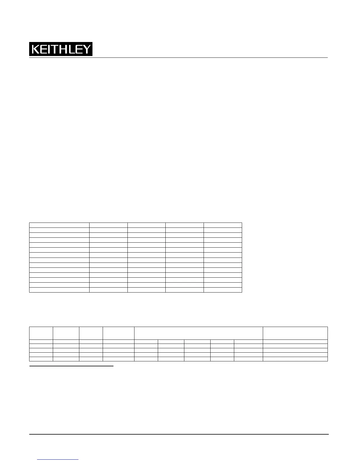
2002 SPECIFIED CALIBRATION INTERVALS
Measurement Function 24 Hour
1
90 Day
2
1 Year
2
2 Year
2
DC Volts • • • •
DC Volts Peak Spikes • • •
AC Volts rms •
3
•
3
•
3
AC Volts Peak • • •
AC Volts Average •
3
•
3
•
3
AC Volts Crest Factor • • •
Ohms • • • •
DC Current • • • •
DC In-Circuit Current • • •
AC Current • • •
Frequency • • •
Temperature (Thermocouple) • • •
Temperature (RTD) • • • •
DC VOLTS
DCV INPUT CHARACTERISTICS AND ACCURACY
Enhanced Accuracy
4
– 10PLC, DFILT 10
Relative Accuracy
±(ppm of reading + ppm of range)
Range Full Scale Resolution Input Resistance
Transfer
5
24 Hours
6
90 Days
7
1 Year
7
2 Years
7
Temperature Coefficient
±(ppm of reading + ppm of range)/°C
Outside TCAL ±5°C
200 mV
8
±210.000000 1 nV >100 G 0.4 + 1.5 3.5 + 3 15 + 8 19 + 9 23 + 10 2 + 1.8
2 V
8
±2.10000000 10 nV >100 G 0.2 + 0.15 1.2 + 0.3 6 + 0.8 10 + 0.9 14 + 1 0.2 + 0.18
20 V ±21.0000000 100 nV >100 G 0.1 + 0.05 1.2 + 0.1 6 + 0.15 10 + 0.15 14 + 0.15 0.3 + 0.02
200 V ±210.000000 1 µV 10 M ±1% 0.5 + 0.08 5 + 0.4 14 + 2 22 + 2 30 + 2 1.5 + 0.3
1000 V
9
±1100.00000 10 µV 10 M ±1% 1 + 0.05 5 + 0.08 14 + 0.4 22 + 0.4 30 + 0.4 1.5 + 0.06
1
For T
CAL
±
1°C.
2
For T
CAL
±
5°C.
3
For ±2°C of last AC self-cal.
4
Specifications are for 10 power line cycles, synchronous autozero, 10-reading repeat digital filter, autorange off, except as noted.
5
Specifications apply for 20-reading repeat digital filter, TREF ± 0.5°C (TREF is the initial ambient temperature), and for measurements within 10% of the initial
measurement value and within 10 minutes of the initial measurement time.
6
For T
CAL
±1°C, following 4-hour warm-up. TCAL is ambient temperature at calibration (23°C at the factory). Add 0.5 ppm of reading uncertainty if the unit is power
cycled during this interval.
7
For T
CAL
±5°C, following 4-hour warm-up.
8
Care must be taken to minimize thermal offsets due to operator cables.
9
Add 20ppm × (VIN/1000V)
2
additional uncertainty for inputs above 200V, except in transfer accuracy specifications