Front Panel Operation
2-52
.
For this example, the Models 2002 and 7001/7002 are con-
figured as follows:
Model 2002:
Idle State:
Bench reset = :INIT:CONT ON*
Arm layer:
Arm source = Immediate*
Arm count = 1*
Arm trigger control = Acceptor*
Scan layer:
Scan source = Immediate*
Scan count = Infinite*
Scan trigger control = Acceptor*
Measure layer:
Measure source = External
Measure count = Infinite*
Measure trigger control = Acceptor*
* Indicates that the setting is the BENCH RESET (and factory) default con-
dition.
Model 7001 or 7002:
Idle State:
Reset = :INIT:CONT OFF*
Scan List = 1!1-1!10,
Arm layer:
Arm spacing = Immediate*
Arm count = 1*
Arm trigger control = Acceptor*
Scan layer:
Scan spacing = Immediate*
Number of scans = 1
Scan trigger control = Acceptor*
Channel Layer:
Channel spacing = External
Number of channels = Use Scanlist length*
Channel trigger control = Source*
* Indicates that the setting is the RESET (and factory) default condition.
Notice that the Model 2002 is reset to BENCH defaults. With
this selection, the multimeter stays armed. Since the arm
source and scan source are set to Immediate, the Model 2002
waits in the measure layer for a trigger.
With the Channel Trigger Control of the switch system set
for Source, scan operation initially bypasses the need for an
external trigger to close the first channel. Since arm spacing
and scan spacing are set to Immediate, the scan starts as soon
as the scanner is taken out of the idle state by pressing the
STEP key. When the front panel STEP key is pressed:
• The scanner arms and closes the first channel.
• After Channel 1!1 settles, a trigger is sent from Channel
Ready of the Model 7001/7002 to External Trigger
Input of the Model 2002 to trigger a measurement of
DUT #1.
• After the Model 2002 completes the measurement, it
outputs a trigger from Meter Complete Output to Exter-
nal Trigger of the Model 7001/7002, which closes the
next channel.
• After Channel 1!2 settles, a trigger is sent to the Model
2002 to trigger a measurement of DUT #2.
This process continues until all ten channels are scanned and
measured.
The data store capability of the Model 2002 could be used to
store the measurements as they occur. Just press the STORE
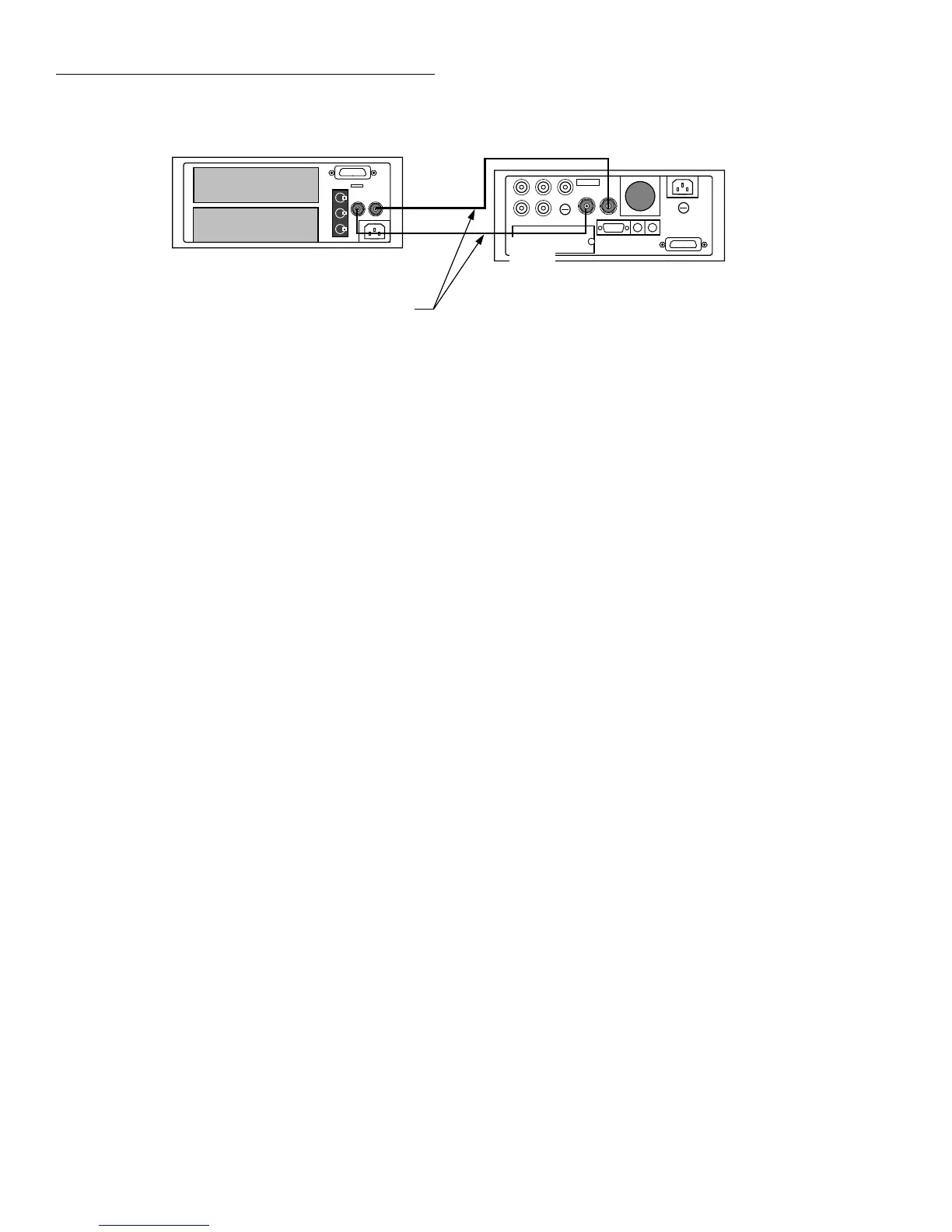
Figure 2-17
External trigger connectors
Channel
Ready
External
Trigger
7001 or 7002 Switch System
7051-2
BNC to BNC
Cables (2)
External
Trigger
Input
Meter
Complete
Output
2002 Multimeter