Front Panel Operation
2-26
IN-CIRCUIT:
In-circuit current is a calculation based on a
4-wire resistance measurement and a voltage measurement.
It is similar to an offset-compensated ohms measurement.
Table 2-15
DCI and ACI auto resolution
Measurement
function and type Integration time Resolution
DC current 0.01 to <0.02 PLC
0.02 to <0.20 PLC
0.20 to <2.00 PLC
2.00 to 50 PLC
4.5d
5.5d
6.5d
7.5d
DC in-circuit current Not used 5.5d
RMS, average 0.01 to <0.02 PLC
0.02 to <10.00 PLC
10.00 to 50 PLC
4.5d
5.5d
6.5d
Notes:
1. For normal DC current, if the resolution is AUTO and the integration
time is SET-BY-RSLN, the resolution will be 6.5 digits and the integra-
tion time 1.0 PLC.
2. For DC in-circuit current, the integration time setting is ignored.
3. For AC current, if the resolution is AUTO and the integration time is
SET-BY-RSLN, the resolution will be 5.5 digits and the integration
time 1.0 PLC.
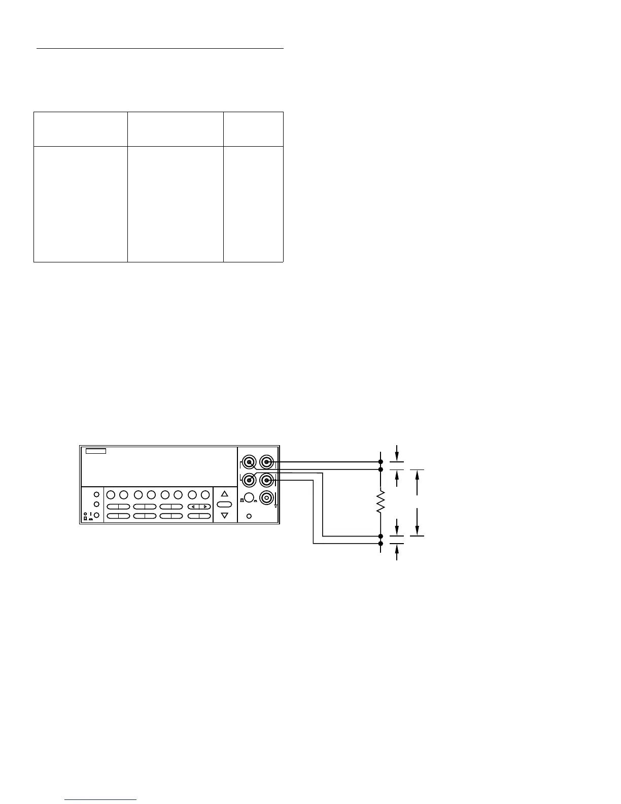
Figure 2-7
DC in-circuit current measurements
NEXT
DISPLAY
PREV
POWER
DCV ACV DCI ACI Ω2 Ω4
FREQ TEMP
REL TRIG STORE RECALL
INFO LOCAL CHAN SCAN CONFIG MENU EXIT ENTER
RANGE
AUTO
FILTER MATH
RANGE
2002 MULTIMETER
SENSE
Ω 4 WIRE
HI
INPUT
LO
INPUTS
CAL
500V
PEAK
F
R
FRONT/REAR
2A 250V
AMPS
350V
PEAK
1100V
PEAK
Model 2002
Circuit
Under Test
Caution : Maximum Input = +200mV on
(I
IN - CKT
+ I
SOURCE
) • R
TRACE
, where
I
SOURCE
= 10mA.
+00.207 ADC ICkt
Trace resistance: 1.0000Ω
Y
Y
x
Note: The distance
"X" must be greater
than 10 times the
distance "Y" or
additional errors will
be introduced.
The current in a low resistance conductor (e.g., a printed
circuit trace) can be measured without breaking the current
path. The Model 2002 can do this with a pair of Kelvin test
probes across the conductor. See Figure 2-7. The method
follows:
1. Using one set of the Kelvin probe tips, the instrument
sources a known current (I
SOURCE
) through the conductor
and simultaneously measures the resulting voltage
(V
MEAS1
) with the other set of probe tips:
or
2. The instrument then measures the voltage (V
MEAS2
)
across the conductor without sourcing an additional
current:
or
V
MEAS1
I
IN-CKT
I
SOURCE
+()R
TRACE
=
R
TRACE
V
MEAS1
I
IN-CKT
I
SOURCE
+()
-------------------------------------------------=
V
MEAS2
I
IN-CKT
()R
TRACE
=
R
TRACE
V
MEAS2
I
IN-CKT
()
----------------------=