Front Panel Operation
2-25
SPEED
The SPEED parameter sets the integration time of the A/D
converter, the period of time the input signal is measured
(also known as aperture). It is discussed in paragraph 2.4.1,
DC and AC voltage. Only the differences for DC and AC cur-
rent are noted here.
SET-BY-RSLN:
This parameter optimizes the integration
time for the present resolution setting. The defaults for set-
by-resolution integration times of DCI and ACI are listed in
Table 2-13.
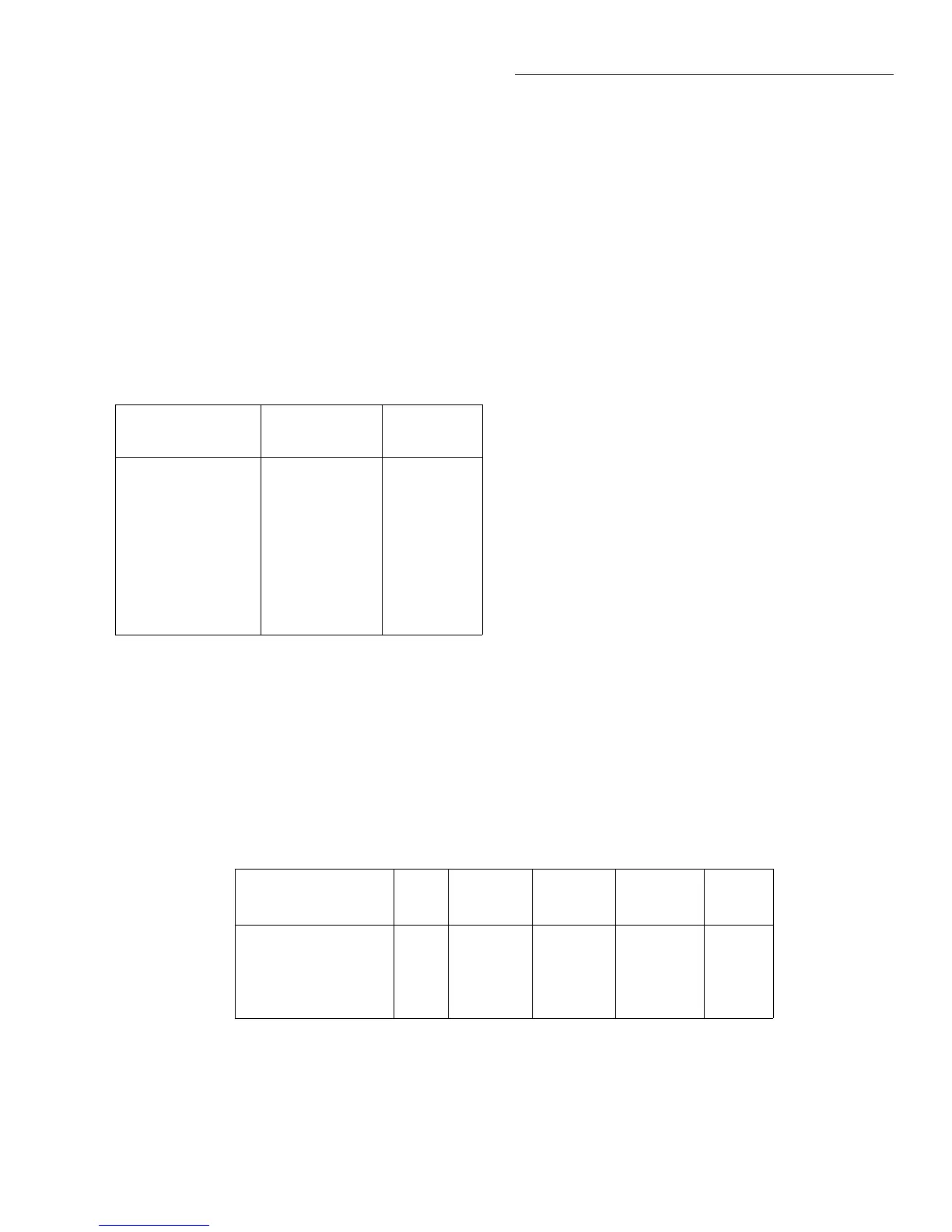
Table 2-13
DCI and ACI integration time set-by-resolution
Measurement
function and type Resolution
Integration
time
DC current 3.5d, 4.5d
5.5d
6.5d
7.5d, 8.5d
0.01 PLC
0.02 PLC
0.20 PLC
2.00 PLC
DC in-circuit current 3.5d to 7.5d Not used
RMS, average 3.5d, 4.5d
5.5d
6.5d, 7.5d, 8.5d
0.01 PLC
0.02 PLC
10.00 PLC
Notes:
1. For normal DC current, if the integration time is SET-BY-RSLN and
the resolution is AUTO, the integration time will be 1.0 PLC and the
resolution 6.5 digits.
2. For DC in-circuit current, the integration time setting is ignored.
3. For AC current, if the integration time is SET-BY-RSLN and the res-
olution is AUTO, the integration time will be 1.0 PLC and the reso-
lution 5.5 digits.
Table 2-14
DCI and ACI auto filter
Measurement
function and type State Type Readings
Noise
tolerance Mode
DC current On Advanced 10 1.0% Moving
DC in-circuit current On Advanced 10 1.0% Moving
AC current Off Advanced 10 5.0% Moving
FILTER
FILTER lets you set the digital filter response. The filter
menu is available from the function configuration menus (i.e.
CONFIGURE DCI) or by pressing CONFIGURE FILTER
with the desired function already selected. All of the param-
eters (menu items) for FILTER are explained in paragraph
2.9. Since the AUTO parameter has specific effects on DCI
and ACI, it is covered here.
AUTO:
This parameter for a digital filter optimizes its use
for the present measurement function. The defaults for auto-
matic filtering of DCI and ACI are listed in Table 2-14.
RESOLUTION
The RESOLUTION parameter sets the display resolution. It
is discussed in paragraph 2.4.1, DC and AC voltage. Only the
differences for DC and AC current are noted here.
AUTO:
Refer to Table 2-15 for the resolution associated
with the integration time.
MEASUREMENT-MODE
This option selects the DC current measurement mode,
either normal or in-circuit measurements.
NORMAL:
This option is for normal current measuring,
where the meter is placed in series with the current path and
the voltage across an internal shunt resistor is measured.