Front Panel Operation
2-28
2.4.3 Two and four-wire resistance
The Model 2002 can make 2-wire resistance measurements
from 100nΩ to 1.05GΩ and 4-wire resistance measurements
from 100nΩ to 2.1MΩ. The basic measurement procedures
for Ω2 and Ω4 are contained in the Getting Started manual.
Shielding
It helps to shield resistance greater than 100kΩ to achieve a
stable reading. Place the resistance in a shielded enclosure
and electrically connect the shield to the INPUT LO terminal
of the instrument.
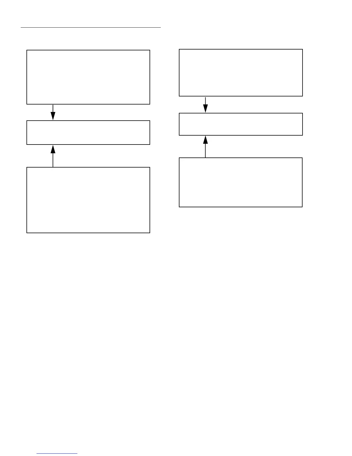
Figure 2-8
AC current multifunction multiple displays
RMS (or AVG)
RANGE = Set by ACI range (auto or fixed).
Autoranges independently of other function.
REL = Operates normally.
SPEED = Set by ACI speed.
FILTER = Set by ACI filter.
RESOLUTION = Set by ACI resolution.
COUPLING = Set by ACI coupling.
AC-TYPE = Set by ACI AC-Type.
FREQ
RANGE = Set by MAX-SIGNAL-LEVEL in CONFIGURE
FREQUENCY menu.
Autorange has no effect.
REL = No effect.
TRIGGER LEVEL = Set while in FREQ. Not available in
CONFIGURE FREQUENCY menu.
FILTER = Unaffected by ACI filter. FREQ has no filter.
RESOLUTION = Fixed at 5 digits.
COUPLING = Set by ACI coupling.
INPUT TERMINALS = Fixed on CURRENT
+000.000 µAAC RMS (or AVG)
+0.0000 Hz
A. AC RMS (or average) current and frequency
functions
B. AC RMS and average current functions
RMS
RANGE = Set by ACI range (auto or fixed).
Autoranges independently of other function.
REL = Operates normally.
SPEED = Set by ACI speed.
FILTER = Set by ACI filter.
RESOLUTION = Set by ACI resolution.
COUPLING = Set by ACI coupling.
AVG
RANGE = Set by ACI range (auto or fixed).
Autoranges independently of other function.
REL = No effect.
SPEED = Set by ACI speed.
FILTER = Unaffected by ACI filter.
RESOLUTION = Fixed at 5.5 digits.
COUPLING = Set by ACI coupling.
+000.000 µAAC RMS
AVG=000.000 µAAC
Resistance configuration
The following information explains the various configura-
tion options for 2-wire and 4-wire resistance measurements.
The configuration menus are summarized in Tables 2-16 and
2-17. The menus are accessed by pressing CONFIG and then
Ω2 or Ω4. Paragraph 2.3.5 summarizes the rules for navigat-
ing through the menus.
Note that a function does not have to be selected in order to
be configured. When the function is selected, it will assume
the programmed status.