Front Panel Operation
2-56
External Triggering and Trigger Link
As previously mentioned, the trigger pulses for the asynchro-
nous Trigger Link are identical to the trigger pulses used for
External Triggering. The only thing that prevents them from
being used together in a test system is connection incompat-
ibility. Trigger Link uses 8-pin micro-DIN connectors while
External Triggering uses BNC connectors.
This connection problem can be solved by using the Model
8502 Trigger Link Adapter. The adapter has two 8-pin micro-
DIN connectors and six BNC connectors. The micro-DIN
connectors mate directly to the Trigger Link connector on
the Model 2002 using a trigger link cable. The BNC
connectors mate directly to the External Triggering BNC
connectors on other instruments using standard male BNC to
BNC cables.
Figure 2-22 shows how a Keithley Model 706 Scanner can be
connected to the Trigger Link of the Model 2002 using the
adapter. With this adapter, a Model 706 could be substituted
for the Model 7001/7002 in the previous example (Asyn-
chronous Trigger Link example #1). With the Model 706 set
for External Triggering, the test would start when the single
scan mode is selected and initiated.
Asynchronous Trigger Link example #2
In this example, the test system (Figure 2-23) includes a
Model 2002 to measure each DUT at two different bias lev-
els that are provided by a Model 230 voltage source. With the
source set to the first voltage level, the ten channels are
scanned and measured. The source is then set to the second
voltage level and the ten channels are again scanned and
measured.
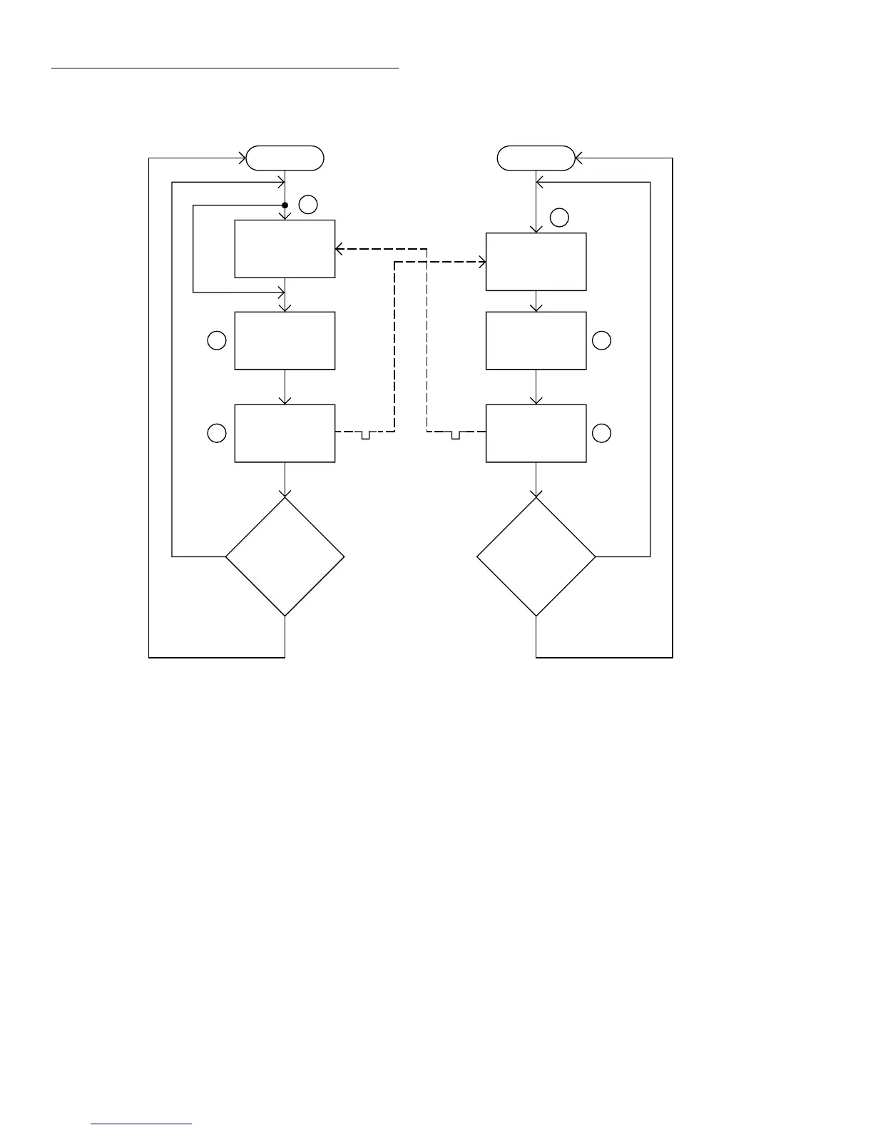
Figure 2-21
Operation model for asynchronous trigger link example #1
Idle
Bypass
B
Wait for
Trigger Link
Trigger
Scan
Channel
C
Output
Trigger
Trigger
D
No
Scanned
10
Channels
?
Yes
7001or 7002
Make
Measurement
Made
10
Measurements
?
2002
Press STEP to start scan
Arm
A
Wait for
Trigger Link
Trigger
E
Output
Trigger
Trigger
F
No
Yes